Base station, receiving device, mobile terminal, and frequency sharing method
A receiving device and base station technology, which is applied in the field of receiving devices and base stations, can solve the problems of not considering the frequency band transmission status, not considering the transmission parameters, and it is difficult to improve the efficiency of frequency use, etc.
- Summary
- Abstract
- Description
- Claims
- Application Information
AI Technical Summary
Problems solved by technology
Method used
Image
Examples
no. 1 approach
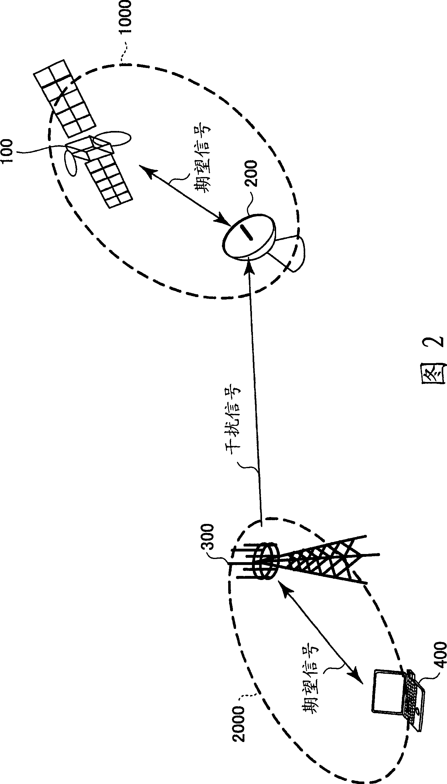
[0041] A wireless communication system according to a first embodiment of the present invention is described below with reference to FIG. 2 .
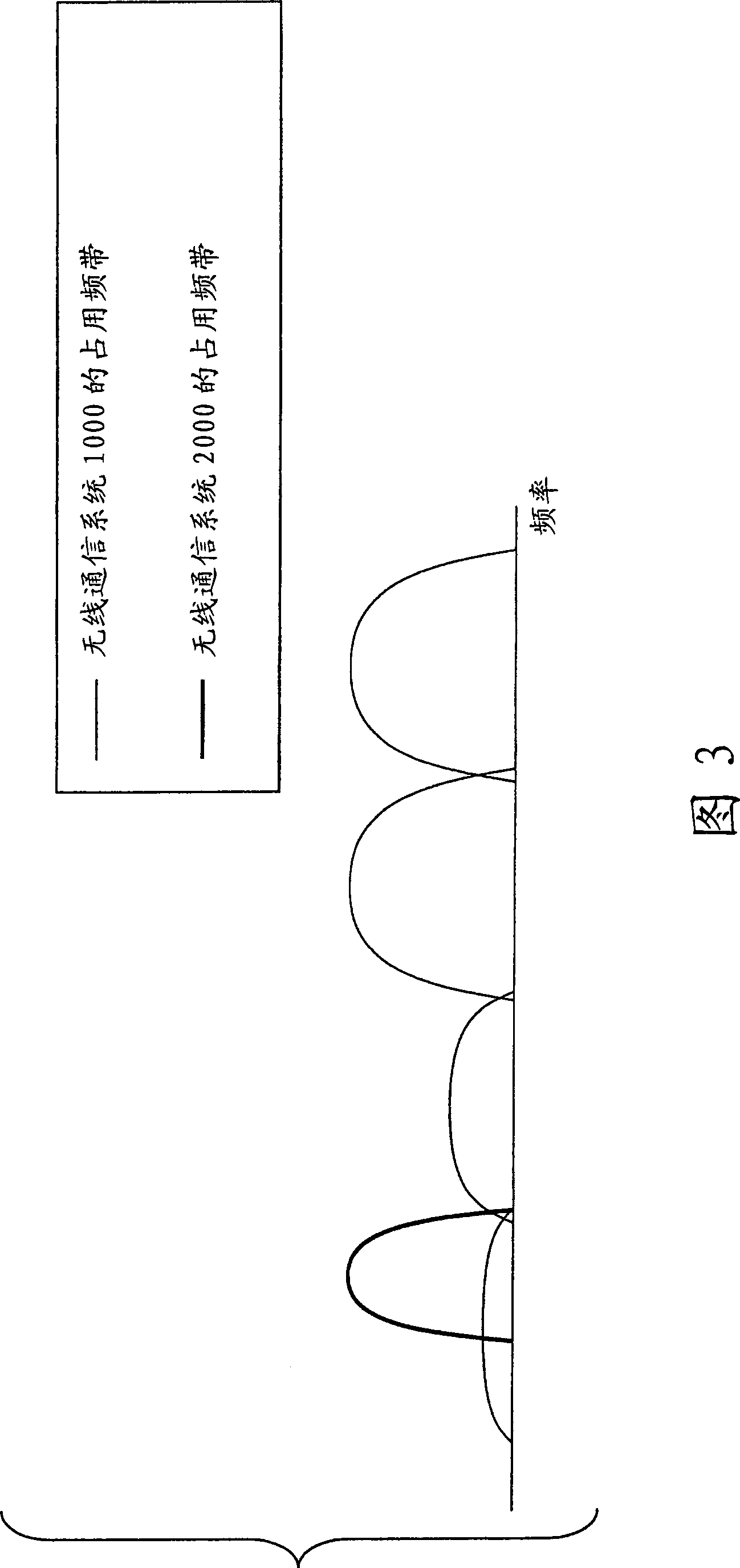
[0042] The wireless communication system 2000 of this embodiment is used in the same and / or near (adjacent) area as the area where the wireless communication system 1000 is used. Furthermore, as shown in FIG. 3 , the wireless communication system 2000 uses the same and / or close (adjacent) frequency band as the frequency band used by the wireless communication system 1000 .
[0043] In this embodiment, the wireless communication system 1000 represents an existing wireless communication system, and has priority over the wireless communication system 2000 . In the example shown in FIG. 2, the wireless communication system 1000 is represented by a satellite broadcasting system, and the wireless communication system 2000 is represented by a mobile communication system.
[0044] The wireless communication system 1000 includes a transmitting...
no. 2 approach
[0073] A wireless communication system according to a second embodiment of the present invention will be described below.
[0074] The configuration of the wireless communication system of this embodiment is basically the same as that described with reference to FIG. 2 . Also, the configuration of the base station 300 of this embodiment is basically the same as that described with reference to FIG. 4 .
[0075] In the first embodiment, the maximum transmission power is determined based on the distance between the receiving device 200 of the wireless communication system 1000 and the transmitting device of the base station 300 of the wireless communication system 2000 . However, in practice, as shown in FIG. 7 , the degree of influence exerted by the transmitting device of the base station 300 of the wireless communication system 2000 on the receiving device 200 of the wireless communication system 1000 depends on, for example, the height difference between the receiving device...
no. 3 approach
[0083] A wireless communication system according to a third embodiment of the present invention will be described below.
[0084] The configuration of the wireless communication system of this embodiment is basically the same as that described with reference to FIG. 2 . Also, the configuration of the base station 300 of this embodiment is basically the same as that described with reference to FIG. 4 .
[0085] In the above implementation manners, the maximum transmit power is determined based on the interference of spurious signals to the wireless communication system 1000 .
[0086] However, there are cases where the influence of out-of-band signals outside the operating frequency band received by the receiving apparatus 200 is greater than the influence of spurious signals within the operating frequency band. The effect of this out-of-band signal is called desensitization. Desensitization is a form of interference that occurs when non-linear elements of the receiving appar...
PUM
 Abstract
Description
Claims
Application Information
 - R&D
- Intellectual Property
- Life Sciences
- Materials
- Tech Scout
- Unparalleled Data Quality
- Higher Quality Content
- 60% Fewer Hallucinations
Browse by: Latest US Patents, China's latest patents, Technical Efficacy Thesaurus, Application Domain, Technology Topic, Popular Technical Reports.
© 2025 PatSnap. All rights reserved.Legal|Privacy policy|Modern Slavery Act Transparency Statement|Sitemap|About US| Contact US: help@patsnap.com


