Living body observing device

A technology for observing devices and living organisms, which can be used in instruments, televisions, applications, etc., and can solve problems such as reduced sensitivity characteristics and reduced illumination light in blue wavelength bands.

Active Publication Date: 2011-03-02
OLYMPUS CORP
View PDF3 Cites 0 Cited by
  • Summary
  • Abstract
  • Description
  • Claims
  • Application Information

AI Technical Summary

Problems solved by technology

[0007] However, for example, in the device described in the aforementioned Japanese Patent Application Laid-Open No. 2003-93336, in the illumination optical system for irradiating the subject with illumination light from a lamp and the imaging optical system for capturing the subject image, for example, due to the blocking The transmission characteristics of the light guide of the endoscope for near-ultraviolet light and the transmission characteristics of the infrared cut filter inserted in the light path of the light source, etc., often reduce the amount of illumination light in the blue wavelength band, and the sensitivity characteristics of the CCD are also in the blue wavelength band. Since the frequency band is lowered, when the spectral image of this blue wavelength band is generated from the captured image information, there is a problem that the S / N is relatively low compared with spectral images of other wavelength bands

Method used


Image

  • Living body observing device
  • Living body observing device
  • Living body observing device

Examples


Embodiment 1

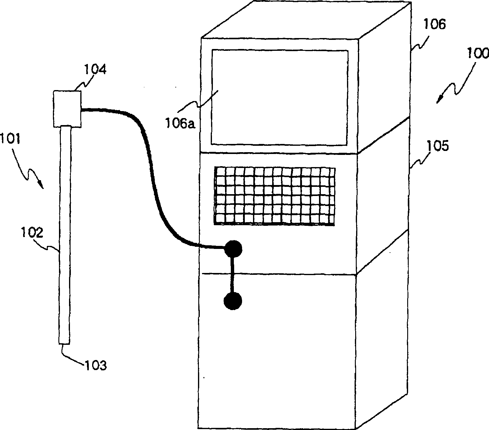
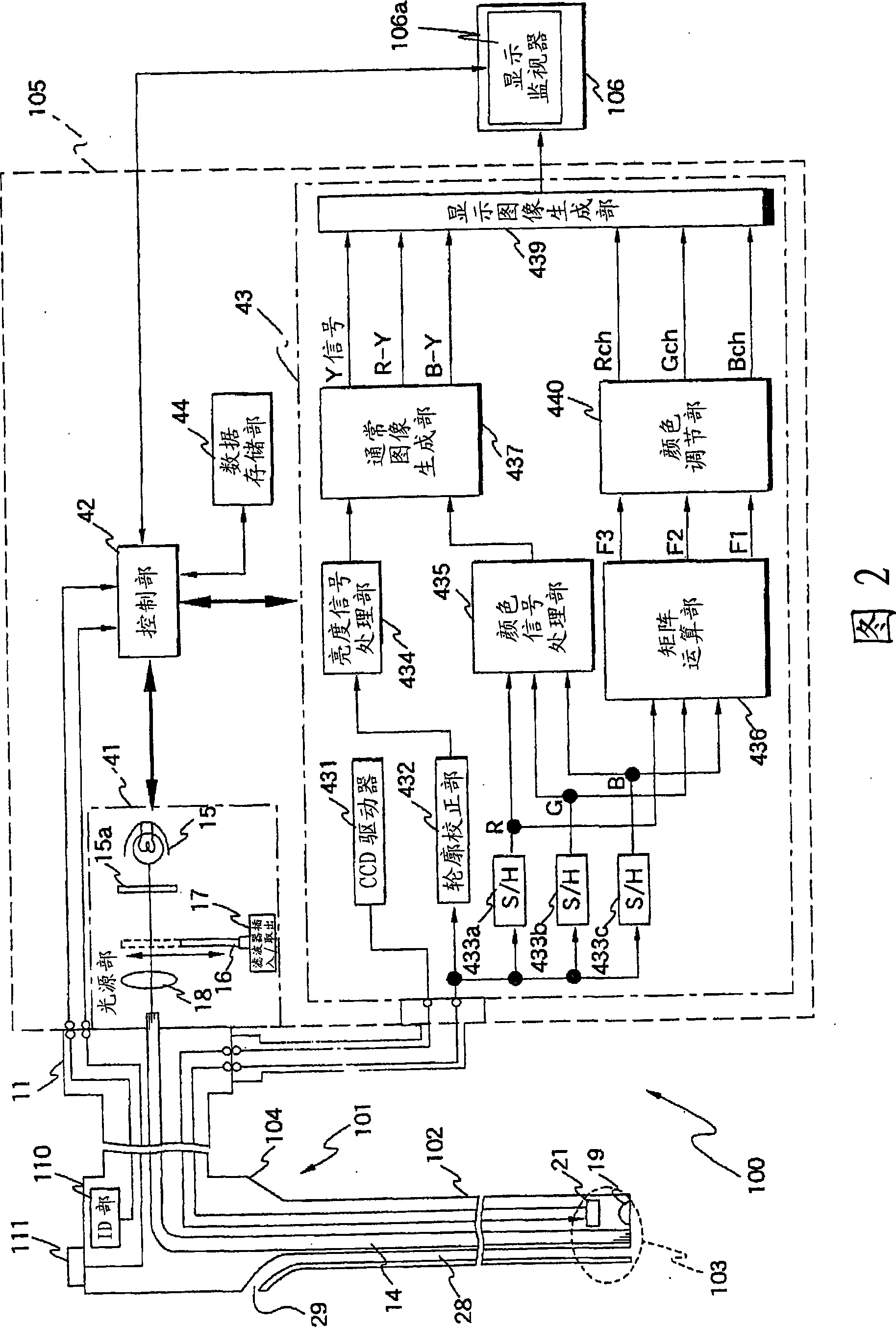
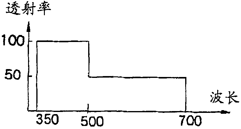
[0055] Figure 1 to Figure 36 Relating to embodiment 1 of the present invention, figure 1 is an external view showing the external appearance of the electronic endoscope device, figure 2 is showing figure 1 Block diagram of the structure of the electronic endoscopy device, image 3 is showing figure 2 A graph of the transmission characteristics of the light limiting filter, Figure 4 is shown in figure 2 A diagram of the arrangement of the color filters set on the front surface of the CCD, Figure 5 is description figure 2 A diagram of the matrix calculation method for calculating the matrix in the matrix operation section of , Image 6 is shown by figure 2 A diagram of the spectral characteristics of the spectral image generated by the matrix operation unit, Figure 7 is shown by figure 2 A diagram of the layered structure of biological tissue observed by the electronic endoscope device, Figure 8 is the description from figure 2 A diagram of the state in w...

Embodiment 2

[0154] Figure 37 ~ Figure 43 Relating to embodiment 2 of the present invention, Figure 37 is a block diagram showing the configuration of the electronic endoscope device, Figure 38 is showing Figure 37 A diagram of the structure of the RGB rotation filter, Figure 39 It shows the transmission of the first spectral image generation mode, that is, when there is no light quantity limiting filter on the optical path. Figure 38 A plot of the spectral properties of light for an RGB spin filter, Figure 40 It shows the transmission of the second spectral image generation mode, that is, when there is a light quantity limiting filter on the optical path. Figure 38 A plot of the spectral properties of light for an RGB spin filter, Figure 41 is showing Figure 37 A block diagram of the structure of a modification of the electronic endoscope device, Figure 42 is showing Figure 41 A diagram of the structure of the RGB rotation filter, Figure 43 is showing Figure 38 A dia...


PUM


Abstract

A light source unit (41) connected with a control unit (42) and an endoscope (101) emits whit light with a specified light quantity based on a signal from the control unit (42). The light source unit (41) comprises a lamp (15) as a white light source, an infrared cutting filter (15a), a light quantity limiting filter (16) inserted / removed into / from a light path to limit a light quantity in a specified wavelength region of white light, a filter inserting / removing drive unit (17) for inserting / removing the light quantity limiting filter (16) into / from the light path, and a condenser lens (18) for emitting white light. For example, the light quantity limiting filter (16) limits, when transmittance in a blue band is 100%, transmittance in the other bands to 50%. Accordingly, an S / N in a visible light region in generating a discrete spectral image by a lighting light is improved.

Description

technical field [0001] The present invention relates to a living body observation device which utilizes color image signals obtained by photographing a living body and displays them as spectral images on a display device through signal processing. Background technique [0002] Conventionally, as a living body observation device, an endoscope device that irradiates illumination light to obtain an endoscopic image of the inside of a body cavity has been widely used. In such an endoscope device, an electronic endoscope having an imaging section that introduces illumination light from a light source device into a body cavity using a light guide or the like, and photographs a subject with the returned light is used. The scope device performs signal processing on an imaging signal from the imaging unit by a video processor, displays an endoscopic image on an observation monitor, and observes an observation site such as an affected area. [0003] In the case of performing normal b...

Claims


Application Information

Patent Timeline
Patent Type & Authority Patents(China)
IPC IPC(8): A61B1/04H04N7/18G02B23/24
CPCG02B23/24A61B1/00009A61B1/063A61B1/0646H04N2005/2255A61B1/0638H04N5/2256A61B1/000094A61B1/044A61B1/0655H04N23/56H04N23/555A61B1/04H04N7/18
Inventor 山崎健二后野和弘浦崎刚竹村尚
Owner OLYMPUS CORP
Why Eureka
Try Eureka