
Orientation analysis meter

An analyzer and orientation technology, which is applied in the field of orientation analyzers, can solve problems such as inability to miniaturize, difficulty in ensuring accuracy, and bulky parts, and achieve the effects of improving S/N, ensuring accuracy, and reducing parts cost

Active Publication Date: 2009-07-01
YOKOGAWA ELECTRIC CORP
View PDF5 Cites 0 Cited by
  • Summary
  • Abstract
  • Description
  • Claims
  • Application Information

AI Technical Summary

Problems solved by technology

[0013] Due to the high cost of the A / D converter and the bulky parts, there is a problem that it cannot be miniaturized
[0014] In addition, there are also methods of investigating the orientation by using the dielectric coefficient, the propagation speed of ultrasonic waves, or microwaves, but there are still problems such as not being suitable for online high-speed measurement, and it is difficult to ensure accuracy.

Method used


Image

  • Orientation analysis meter
  • Orientation analysis meter
  • Orientation analysis meter

Examples


Embodiment Construction

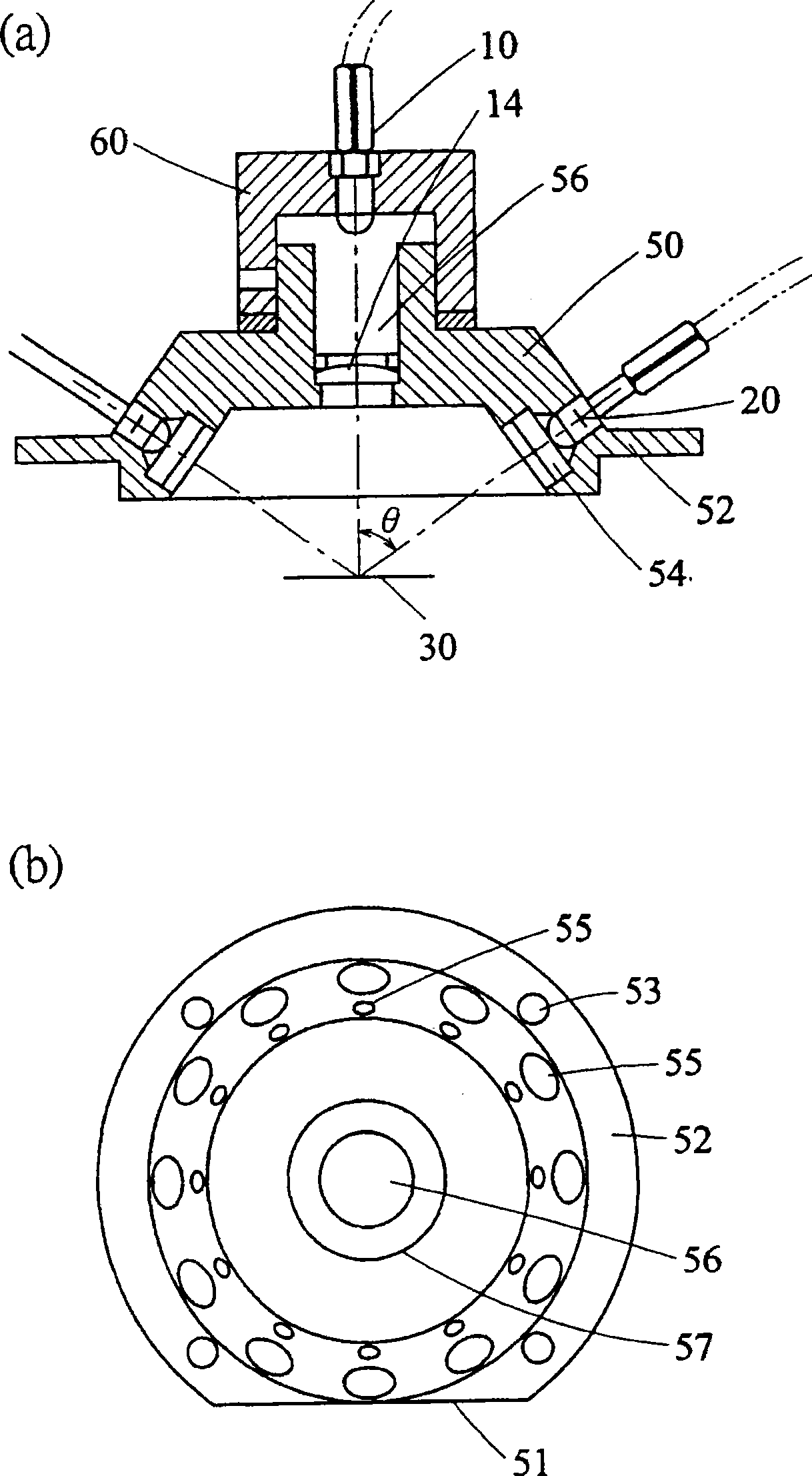
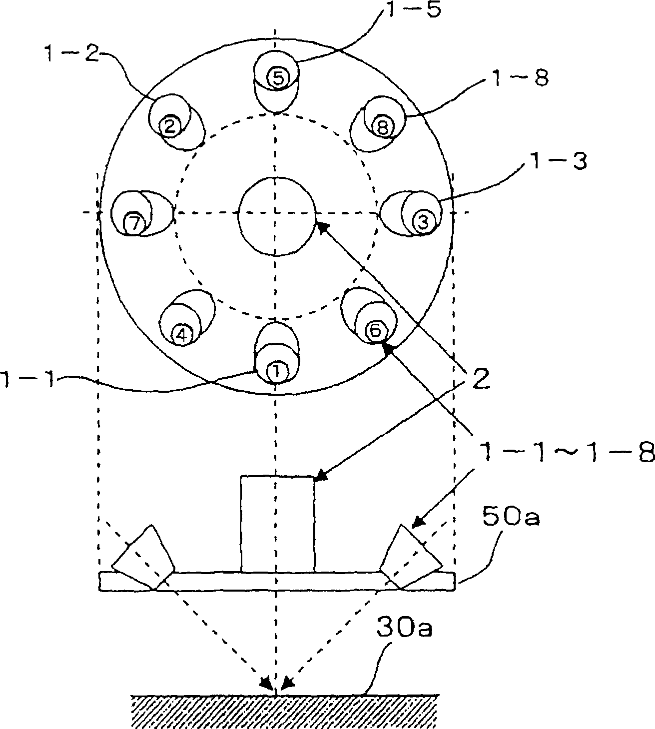
[0070] The present invention will be described in detail below in conjunction with the accompanying drawings. image 3 It is a configuration diagram of an important part of the orientation analyzer related to the present invention.

[0071] image 3 Among them, 1-1 to 1-8 are light-emitting modules such as LEDs or lasers, and 50a is a disk-shaped light-emitting module fixing plate. 2 is a light-receiving element composed of a light-receiving diode or the like, and the light-emitting elements 1-1 to 1-8 are arranged at equal intervals around the periphery of the disk-shaped light-emitting element fixing plate 50a. In order to make the light energy emitted by these light-emitting components roughly irradiate the same position of the planar sample 30a, the light-emitting components are arranged at a predetermined angle with the planar sample, and a part of the scattered light reflected by the planar sample 30a will be formed by the arrangement. It is received by the light-recei...


PUM


Abstract

An orientation analyzer, which can quickly measure the fiber orientation of paper, the molecular orientation of film, or the orientation of fillers in plastics, reducing the cost and volume of parts. The orientation analyzer of the present invention measures the object to be measured based on a light-emitting assembly that irradiates light to the object to be measured, a light-receiving assembly that receives reflected light reflected by the object to be measured, and a signal from the light-receiving assembly. Orientation of objects, wherein multiple light emitting components are arranged around the light receiving component.

Description

technical field [0001] The present invention relates to an orientation analyzer for measuring the fiber orientation of films or papers using an optical non-contact method, and relates to an orientation analyzer capable of achieving high speed, high precision, miniaturization, and low cost. Background technique [0002] The orientation analyzer is used to measure the fiber orientation of paper, the molecular orientation represented by plastic films, the orientation of different blending degrees including fibrous fillers or other fillers mixed in reinforced plastics, and the orientation of liquid crystal films. An instrument for the orientation characteristics produced by rubbing treatment, etc. Ways to measure orientation include ultrasonic waves, microwaves, transmitted light, reflected light, and microscopes. [0003] The prior art related to a fiber orientation analyzer that optically and non-contactly measures the fiber orientation of paper is as follows. [0004] (Pate...

Claims


Application Information

Patent Timeline
Patent Type & Authority Patents(China)
IPC IPC(8): G01N21/47G01B11/00G01B11/26
Inventor 仁神铁人土屋彰彦大日方佑彦
Owner YOKOGAWA ELECTRIC CORP
Learn More