Hoisting and piling structure of container

A container and stacking technology, which is applied in the field of container lifting and stacking structures, can solve problems such as low precision, corner ears 21 not centered, large process rounded corners, etc., to achieve simple assembly and avoid assembly process problems , the effect of connection strengthening

Active Publication Date: 2009-04-08
CHINA INTERNATIONAL MARINE CONTAINERS (GROUP) CO LTD
View PDF0 Cites 6 Cited by
  • Summary
  • Abstract
  • Description
  • Claims
  • Application Information

AI Technical Summary

Problems solved by technology

[0004] In the prior art, the connection method between the corner fittings 1, 2 and the corner post 3 is widely used because of its high reliability, but in the actual production process of the container, the assembly method of the corner fittings 1, 2 and the corner post 3 is difficult in the process. There are often some problems on the
Since the corner pieces 1 and 2 are both castings, the precision is not high, and due to the process requirements of the casting itself, there will be a large process fillet at the intersection 24 of the corner piece ear 21 and the small boss 22
Due to the presence of rounded corners, when the corner fittings 1 and 2 are assembled with the corner post 3, the inner surface 25 of the corner post 3 cannot be well attached to the outer surface of the ear 21, and the end 26 of the corner post 3 cannot reach the corner fitting surface 27. , cannot meet the requirements of the assembly process
If the notch 23 of the corner post is enlarged so as to avoid rounded corners during assembly, the weld seam 28 will be very thick, the appearance of the weld will be ugly, and the weld quality cannot be guaranteed.
Sometimes due to casting, the corner ear 21 is not centered, and even the corner ear 21 cannot fit with the corner post gap 23 at all.

Method used


Image

  • Hoisting and piling structure of container
  • Hoisting and piling structure of container
  • Hoisting and piling structure of container

Examples


Embodiment Construction

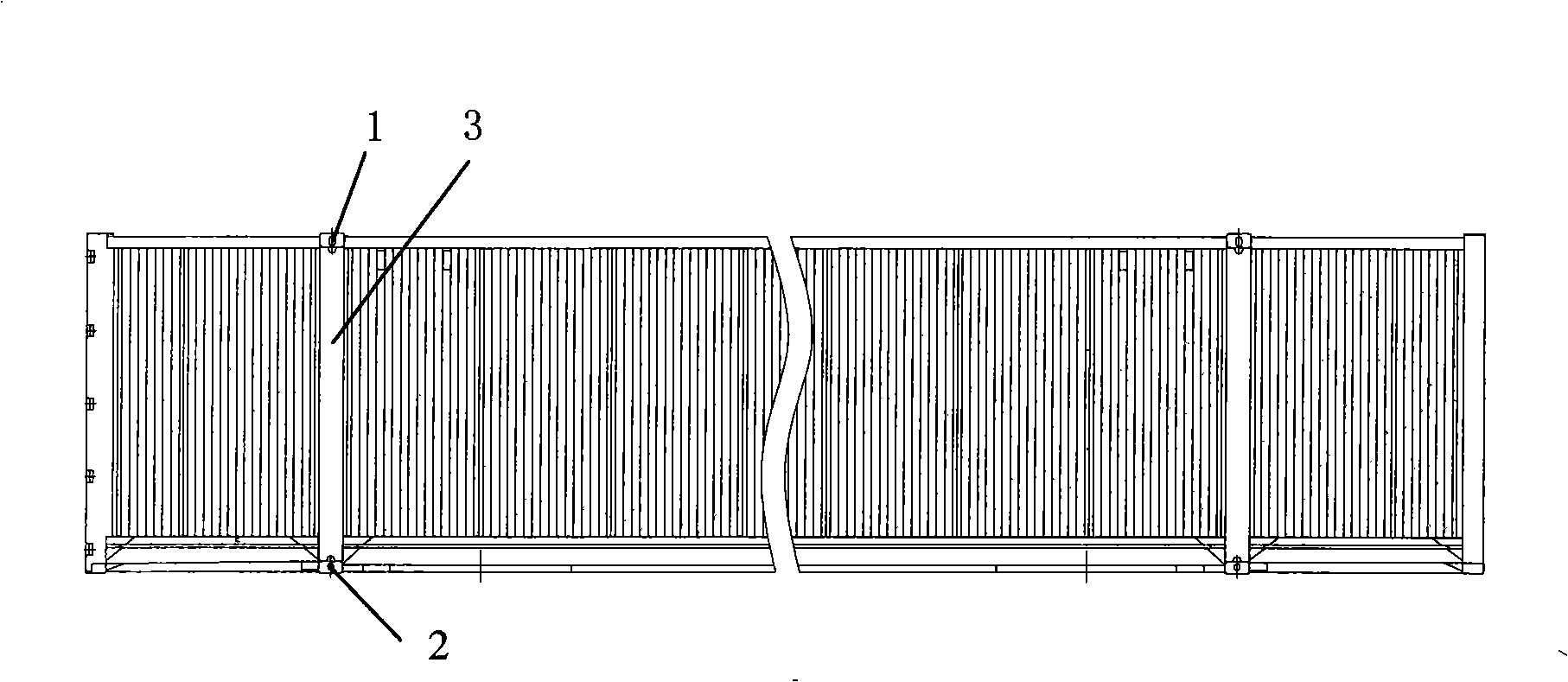
[0035] Such as Figure 9-12 As shown, in the first embodiment of the present invention, the container lifting and stacking structure includes corner posts 6 , top corner pieces 4 and bottom corner pieces 5 respectively located at the top and bottom of the corner posts 6 . The corner post 6 includes an inner corner post 61 and an outer corner post 62 parallel to each other. Both the top corner piece 4 and the bottom corner piece 5 have ears for welding with the corner post 6 . A first ear 41 extending downward is provided on the bottom surface of the top corner piece 4 , and a second ear 51 extending upward is provided on the bottom corner piece 5 . The shapes of the two ears 41, 51 may be trapezoidal, rectangular or other shapes. There is a certain distance between the first ear 41 and the outer surface of the corner piece 4 for placing the upper end of the outer corner post 62 . There is also a certain distance between the second ear 51 and the outer surface of the bottom ...


PUM


Abstract

The invention relates to a hoisting and stacking structure of a container, which comprises a corner post, a top angle piece and a bottom angle piece arranged on the top and the bottom of the corner post respectively, wherein a first ear is arranged on the top angle piece extending downwardly; a second ear is arranged on the bottom angle piece extending upwardly; and the first ear and the second ear both extend into the corner post and are welded with the inner surface of the corner post. The hoisting and stacking structure of the container increases the weld length between the corner post and the top angle piece, as well as the bottom angle piece, so as to strength the connecting between among the corner post and the top angle piece as well as the bottom angle piece. Because of the simple plane fit between the first ear together with the second ear and the corner post, the problem of imprecise assembly can not happen; moreover, even if the precisions of the top angle piece and bottom angle piece are reduced, the assembly of the corner post can not be affected, thereby avoiding the problem of the assembly process caused by the difference of casting the angle piece, and ensuring the convenient and simply assembly of the angle piece with ears and the corner post.

Description

technical field [0001] The invention relates to the field of containers, more specifically, to a container lifting and stacking structure. Background technique [0002] Traditional containers are manufactured according to the size requirements of the ISO standard. The width of the box body is 2438mm. When lifting with the corner fittings on the top of the box, the center distance of the lifting and stacking holes is 2260mm. However, in recent years, some ultra-wide boxes that have appeared in North America or Europe have a box width of 2591mm or even 2600mm. In order to use the existing ISO lifting equipment, the lifting and stacking center distance of the supporting corner parts is still required to be 2260mm. As a result, the bending moment M suffered by the corner fittings under the action of the lifting force F and the weight G of the box increases, which puts forward higher requirements for the strength of the weld at the joint between the corner fittings and the corner...

Claims


Application Information

Patent Timeline
IPC IPC(8): B65D90/00B65D88/12
Inventor 孔河清黎泽深邵兴意
Owner CHINA INTERNATIONAL MARINE CONTAINERS (GROUP) CO LTD
Why Eureka
Try Eureka