Touch control type substrates, colored optical filtering substrates and touch control type LCD

A technology of color filter substrate and color filter layer, which is applied in the direction of static indicators, optics, instruments, etc., can solve the problems of reducing the transmission speed of sensing signals, etc., and achieve the problem of improving the sheet resistance value too high and the light transmittance Effect

Active Publication Date: 2009-04-08
AU OPTRONICS CORP
View PDF6 Cites 35 Cited by
  • Summary
  • Abstract
  • Description
  • Claims
  • Application Information

AI Technical Summary

Problems solved by technology

However, the above-mentioned method will increase the sheet resistance of the conductive film layer in the capacitive sensing layer, and relatively

Method used


Image

  • Touch control type substrates, colored optical filtering substrates and touch control type LCD
  • Touch control type substrates, colored optical filtering substrates and touch control type LCD
  • Touch control type substrates, colored optical filtering substrates and touch control type LCD

Examples


no. 1 example

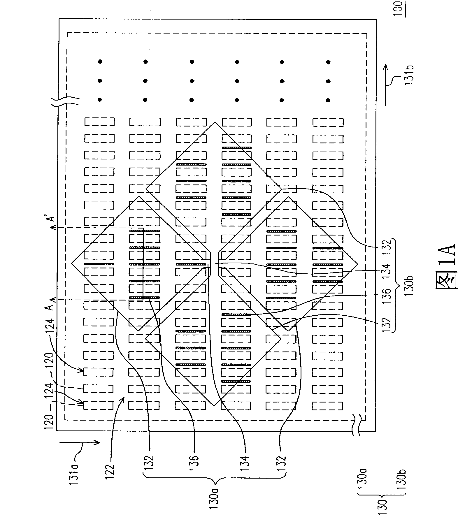
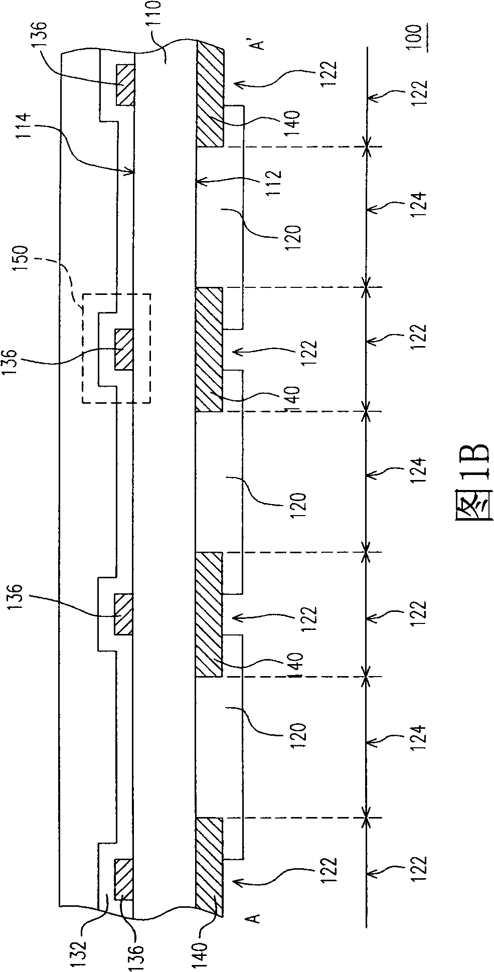
[0059]FIG. 1A shows a partial top view of a color filter substrate according to an embodiment of the present invention, and FIG. 1B is a schematic cross-sectional view of the color filter substrate shown along line AA' in FIG. 1A , wherein the color filter substrate shown in FIG. 1A The dotted line area is a perspective view of the first surface of the color filter substrate. In addition, for the convenience of illustration, FIG. 1A mainly shows a schematic diagram of a display block, a patterned color filter layer, a separation area, and a sensing series, while omitting other parts. possible layers. Comparing FIG. 1A and FIG. 1B at the same time, it can be known that the color filter substrate 100 is a double-sided design structure of the touch-sensitive color filter substrate. The structure of the color filter substrate 100 will be described in detail below.

[0060] Please refer to FIG. 1A and FIG. 1B at the same time. The color filter substrate 100 of this embodiment inclu...

no. 2 example

[0088] The touch-sensitive substrate of this embodiment adopts a design concept similar to that of the above-mentioned color filter substrate, but the difference lies in that the touch-sensitive substrate of this embodiment is equipped with sensing series on the substrate, and the above-mentioned patterned color The filter layer is correspondingly arranged on the display area of ​​the transistor array substrate. In other words, the touch-sensitive substrate of this embodiment can be the opposite substrate, and the touch-sensitive substrate mainly provides touch function. The connection relationship of each component of the touch-sensitive substrate will be described in detail below.

[0089] FIG. 5 is a partial top view of a touch-sensitive substrate according to the present invention. For convenience of description, FIG. 5 mainly shows the structure of the display block and the sensing series, while omitting other possible film layers. Please refer to FIG. 5 , the touch-sens...


PUM


Abstract

The invention discloses a touch type baseplate, a color filtration baseplate and a touch type liquid crystal display, wherein, the color filtration baseplate comprises a baseplate, a plurality of picturized color filtration layer and a plurality of sensing serials, the baseplate has a first surface and a second surface corresponding to the first surface, the baseplate has a plurality of display blocks arrayed in arrays, a partition district is formed between display blocks, the picturized color filtration layer is correspondingly arrayed on the display blocks of the first surface, the sensing serials are arrayed on the second surface. The sensing serials form electricity insulation with each other, and each sensing serial comprises a plurality of sensing pads, a plurality of bridge connectors and a plurality of picturized conducting layers, wherein each bridge connector is connected with two adjacent sensing pads, the picturized conducting layers are stacked with the sensing pads and form an electrical connection with the sensing pads, and the picturized conducting layer corresponds with the partition area. The invention also provides the touch type liquid crystal display and the touch type baseplate.

Description

technical field [0001] The invention relates to a touch-sensitive substrate, and in particular to a touch-sensitive substrate capable of being integrated with a color filter substrate or a touch-sensitive liquid crystal display. Background technique [0002] With the rapid development and application of information technology, wireless mobile communication and information home appliances, in order to achieve more convenient, lighter and more humanized purposes, many information products have changed from traditional keyboard or mouse input devices to use A touch panel is used as an input device, and a touch display device is one of the most popular products nowadays. [0003] Existing touch panels can be roughly classified into capacitive, resistive, and photosensitive types, among which capacitive touch panels are the mainstream products. If classified according to the structural composition, the touch panel can be divided into two categories: the added type and the integr...

Claims


Application Information

Patent Timeline
IPC IPC(8): G02F1/1335G02F1/133G06F3/041
Inventor 简钰峰杨敦钧李锡烈黄伟明吴元均
Owner AU OPTRONICS CORP
Why Eureka
Try Eureka