Side-entry light guide plate, and preparation and application thereof

A light guide plate and side-entry technology, which is applied in the field of side-entry light guide plate and its preparation and application, can solve the problem of poor transmittance luminance of the light-emitting surface, light refraction of the light guide plate, low reflection uniformity, and influence on the quality control of liquid crystal display and other issues, to achieve the effect of improving light reflection and refraction, good collection effect, and excellent internal reflection

Active Publication Date: 2018-10-19
苏州亿光源光电科技股份有限公司
View PDF7 Cites 0 Cited by
  • Summary
  • Abstract
  • Description
  • Claims
  • Application Information

AI Technical Summary

Problems solved by technology

The light is emitted from the backlight, propagates in the light guide plate, and refracts, reflects and fully emits on the dot surface, part of the light is absorbed by the light guide plate, and the rest of the light passes through the light guide plate and enters the liquid crystal material, which is realized by the control circuit. Liquid crystal display, but the light refraction and reflection uniformity of the existing light guide plate is low, and the light transmission luminance of the light-emitting surface is poor, which greatly affects the quality control of liquid crystal display

Method used


Image

  • Side-entry light guide plate, and preparation and application thereof
  • Side-entry light guide plate, and preparation and application thereof
  • Side-entry light guide plate, and preparation and application thereof

Examples


Embodiment 1

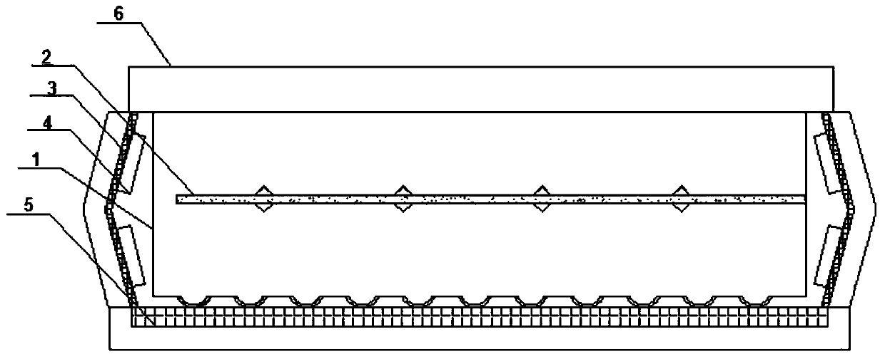
[0030] A side-entry light guide plate. There is a light-transmitting plate inside the light-guide plate. One side of the light-transmitting plate is fixedly connected to the inner wall of the light-transmitting plate (molded integrally during injection). Eight reflective strips are arranged symmetrically on the top and bottom of the light-transmitting plate. There are 4 upper and lower ones. There are several strip grooves on the bottom surface of the light guide plate, and several dots are distributed on the upper and lower surfaces of the light-transmitting plate ( figure 1 ).

[0031] Among them, the light guide plate and the light-transmitting plate are formed by injection molding, the light-guiding plate is made of PMMA material, the light-transmitting plate is made of PC material, and the light transmittance of the light-transmitting plate is 94.7%. The longitudinal section of the bar-shaped groove is set in a "U" shape, and the bar-shaped groove is also densely covered ...

Embodiment 2

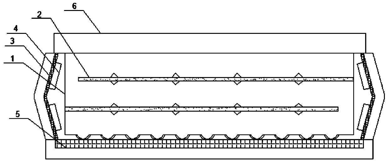
[0034] A side-entry light guide plate. There are two light-transmitting plates inside the light-guide plate. One side of the light-transmitting plate is fixedly connected to the inner wall of the light-transmitting plate (integrated molding during injection). Each light-transmitting plate is symmetrically equipped with eight light-reflecting plates. Strips, 4 upper and lower sides, a number of bar-shaped grooves are provided on the bottom surface of the light guide plate, and a number of dots are distributed on the upper and lower surfaces of the light-transmitting plate ( figure 2 ).

[0035] Among them, the light guide plate and the light-transmitting plate are formed by injection molding, the light-guiding plate is made of PMMA material, the light-transmitting plate is made of PC material, and the light transmittance of the light-transmitting plate is 94.3%. The longitudinal section of the bar-shaped groove is set in a "U" shape, and the bar-shaped groove is also densely c...


PUM

PropertyMeasurementUnit
transmittivityaaaaaaaaaa

Abstract

The invention provides a side-entry light guide plate, and preparation and application thereof. The light guide plate is provided therein with a plurality of baffle light-transmitting plates arrangedin a staggered manner. A plurality of reflective strips are longitudinally symmetrically disposed on each light-transmitting plate. The bottom surface of the light guide plate is provided with a plurality of strip-shaped grooves. A plurality of mesh points are distributed on the lower surface of each light-transmitting plate. The light guide plate is prepared via injection molding. The light guideplate and the light-transmitting plates are all made of PMMA or PC materials. The light-transmitting plates have a light transmittance greater than 94.5%. By reasonable structural design and preparation process parameter adjustment, the side-entry light guide plate has good structural uniformity, good stability, excellent internal reflection and refraction effects, uniform light distribution on alight-emitting surface, and good light transmittance brightness.

Description

technical field [0001] The invention relates to the technical field of side-entry light guide plates, in particular to a side-entry light guide plate and its preparation and application. Background technique [0002] A liquid crystal display device (LCD) has many advantages such as a thin body, power saving, and no radiation, and has been widely used. Most of the liquid crystal display devices currently on the market are backlight liquid crystal display devices, which include a liquid crystal panel and a backlight module. The working principle of the liquid crystal panel is to place liquid crystal molecules between two parallel glass substrates. There are many vertical and horizontal small wires between the two glass substrates. The direction of the liquid crystal molecules is controlled by electrifying or not, and the light of the backlight module is refracted. Come out to generate the picture. Since the liquid crystal panel itself does not emit light, the light source pr...

Claims


Application Information

Patent Timeline
Patent Type & Authority Applications(China)
IPC IPC(8): G02B6/00G02F1/13357
CPCG02B6/0038G02B6/0041G02B6/0043G02B6/0055G02B6/0065G02F1/133615
Inventor 杨为新
Owner 苏州亿光源光电科技股份有限公司
Why Eureka
Try Eureka