

Sunflower type sun tracking device
A sun-tracking, sunflower-style technology, applied in position/direction control, non-electric variable control, instruments, etc., can solve problems such as low efficiency and complex structure, achieve high flexibility, good dust-proof performance, and improve work stability and the effect of service life
Inactive Publication Date: 2010-11-10
CECEP SOLAR ENERGY TECH
View PDF0 Cites 0 Cited by
- Summary
- Abstract
- Description
- Claims
- Application Information
AI Technical Summary
Problems solved by technology
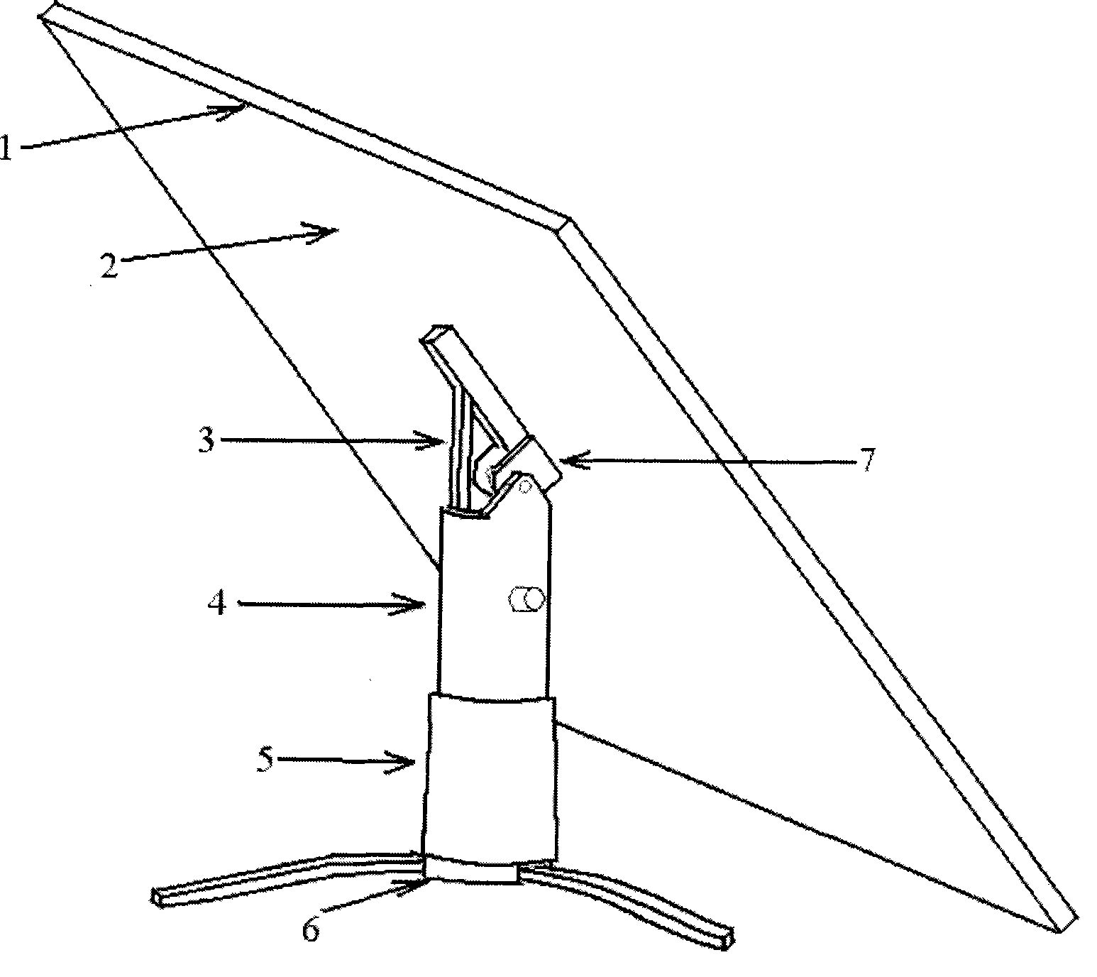
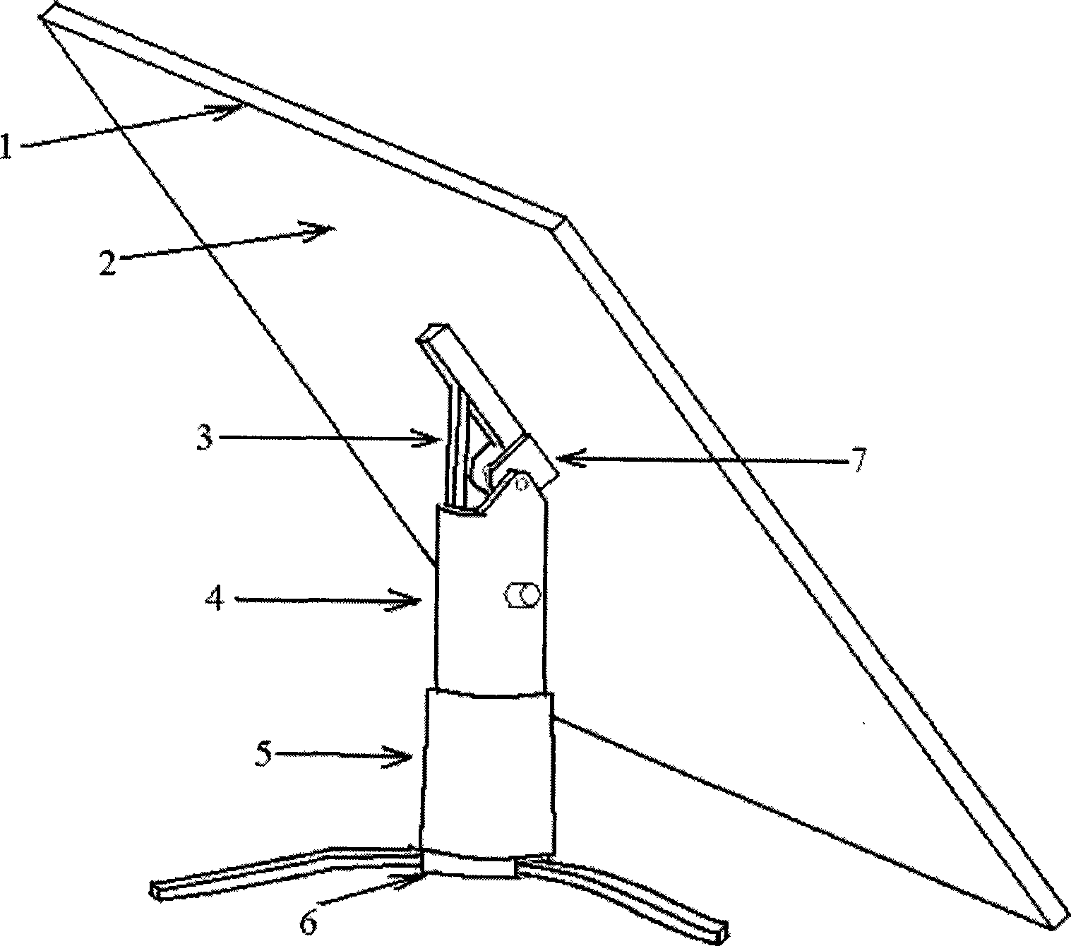
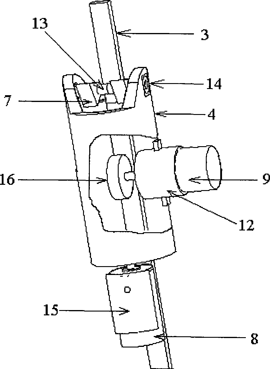
The purpose of the present invention is to provide a sunflower type solar tracking device for the shortcomings of low efficiency and complex structure of the existing solar omnidirectional tracking device, which is characterized in that the back of the solar panel 1 is provided with a roller or a slider running track 2 ; The back center of the solar cell panel 1 is provided with a solar cell panel support frame 7, which is connected with the upper vertical shaft 4 through the central shaft 13 and the bearing 14, and the solar cell panel 1 is fixed on the solar cell panel support frame 7; A movable support rod 3 is arranged in the rotating shaft 4, and one end is embedded in the roller or slider running track 2 through a roller or a slider, and can move on the roller or slider running track 2, and the other end extends into the upper vertical rotating shaft 4 and can be moved The inner side of the support rod 3 is provided with a rack; the horizontal rotation motor 9 is arranged in the middle of the upper vertical rotation shaft 4, and is installed on the horizontal rotation motor mounting base 12, and the horizontal rotation motor mounting base 12 is fixed on the cylinder wall of the upper vertical rotation shaft 4. The motor 9 is connected with a horizontal rotation motor gear 16 which meshes with the rack on the inside of the movable support rod 3, and the horizontal rotation motor 9 drives the movable support rod 3 to move in the vertical direction through the horizontal rotation motor gear 16 to realize the solar cell panel 1. Pitching motion; a ring gear 10 is arranged on the inner cylinder wall at the bottom of the upper vertical shaft 4, and is fixedly connected with the upper vertical shaft 4; a vertical rotation motor 8 is arranged on the inner upper part of the lower vertical rotation shaft 5, and is installed on the vertical rotation motor mount 15, and the vertical rotation motor Mounting seat 15 is fixed on the cylinder wall of lower vertical shaft 5, and vertical motor 8 is connected with vertical motor gear 11, which meshes with ring gear 10, and vertical motor 8 drives ring gear 10 to rotate through vertical motor gear 11, thereby Drive the upper vertical shaft 4 to rotate around its own central axis to realize horizontal and circumferential rotation; the lower vertical shaft 5 is fixedly installed on the base 6
Method used
View moreImage
Smart ImageViewing Examples

Examples
Embodiment Construction
Login to View More PUM
 Abstract
The invention belongs to the field of solar equipment, in particular relates to a solar tracking unit for a solar panel. A running track of an idler wheel or a sliding block is arranged at the back of the solar panel; a supporting frame of the solar panel is arranged in the center of the back of the solar panel and connected with an upper vertical rotating shaft; a supporting bar that can move vertically is arranged in the upper vertical rotating shaft, and one end of the upper vertical rotating shaft is inserted in the running track of the idler wheel or the sliding block by the idler wheel or the sliding block; an electric motor is respectively arranged in the upper vertical rotating shaft and a lower vertical rotating shaft and respectively drives the supporting bar that can move vertically to move up and down and drives the up vertical rotating shaft to rotate by the transmission of gears, so as to realize the luffing movement and horizontal revolution movement of the unit; a photosensor element is arranged on the solar panel and can control the operation of the electric motor by a control circuit, so as to track the sun. Therefore, the unit of the invention can track the sun in all dimensions and receive the sunlight more effectively; and the unit has the advantages of compact mechanical structure, flexible rotation, good dustproof property, etc.
Description
sunflower sun tracker technical field The invention belongs to the field of solar energy equipment, in particular to a sunflower type solar tracking device. Background technique Compared with conventional energy, solar energy has the following advantages: it is the most abundant energy available to human beings; it can be developed and utilized locally without transportation problems; it is a clean energy source that does not produce waste residue, Waste water, exhaust gas, and no noise, will not affect the ecological balance, and will definitely not cause pollution and public nuisance. However, the energy density of solar energy is low, and only when the sunlight is vertically irradiated on the solar panel can the maximum efficiency of solar energy be utilized. Most of the existing sun tracking devices can only track the sun in one direction, and the existing devices that track the sun in all directions have fewer types and more complex structures, and have not made bre...
Claims
Login to View More Application Information
Patent Timeline
 Patent Type & AuthorityPatents(China)
IPC IPC(8): G05D3/00G05D3/12
Inventor郭一竹薛广进
OwnerCECEP SOLAR ENERGY TECH