Wireless transmission system, wireless transmission method, and wireless station and transmitting station used therein

A radio station and wireless transmission technology, applied in the field of wireless transmission system and wireless transmission, and the radio station and transmitting station used therein, can solve the problems of characteristic deterioration, bit error rate deterioration, deterioration, etc., to improve transmission characteristics Effect

Active Publication Date: 2009-04-08
PANASONIC CORP
View PDF2 Cites 1 Cited by
  • Summary
  • Abstract
  • Description
  • Claims
  • Application Information

AI Technical Summary

Problems solved by technology

However, there is a problem that in this conventional transmission diversity, from the standpoint of tolerance (delay tolerance) to the delay dispersion that occurs in the propagation path, due to the The original ability of the way, it is necessary to insert a large delay τ on the sending side in advance s , thus resulting in a significant reduction in the amount of resistance to delay
like Figure 59 As shown in , it is known that the bit error rate deteriorates when a third wave is inserted between two waves compared to when there are two received waves
It can be confirmed that when there are 3 waves, the 3rd wave will not separate the two waves on both sides, bring the same interference, or increase the correlation value, resulting in deterioration
That is, if Figure 55 As shown, there is such a problem that although the transmission wave with up to two delays is ideal, when the third transmission wave is added, the characteristics will deteriorate on the contrary.
[0037] Like this, there is such a problem that when the delay resolution capable of separating delayed wave components and the delay upper limit are intentionally approached, since the maximum number of effective branches that contribute to the path diversity effect is limited to a small number, if a path with a delay is unintentionally added , it will lead to deterioration of transfer characteristics

Method used


Image

  • Wireless transmission system, wireless transmission method, and wireless station and transmitting station used therein
  • Wireless transmission system, wireless transmission method, and wireless station and transmitting station used therein
  • Wireless transmission system, wireless transmission method, and wireless station and transmitting station used therein

Examples


no. 1 approach

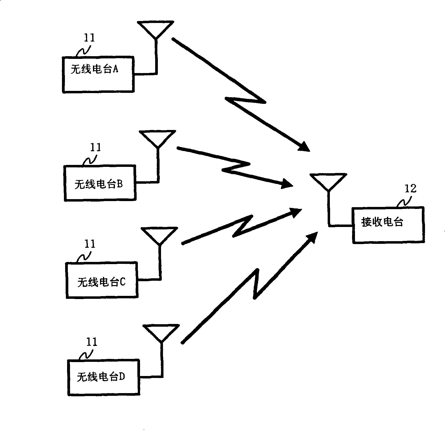
[0117] figure 1 It is a figure which shows the structure of the wireless transmission system which concerns on the 1st Embodiment of this invention. figure 1 The shown wireless transmission system includes a plurality of radio stations 11 and receiving stations 12 . A plurality of radio stations 11 and receiving stations 12 are wirelessly connected together. figure 1 An example in which the number of radio stations 11 is four is shown, and the number of radio stations can be arbitrarily set. Hereinafter, when it is necessary to distinguish the four radio stations 11 , they are represented as radio stations A to D, respectively, and when it is not necessary to distinguish, they are all represented as radio stations 11 .

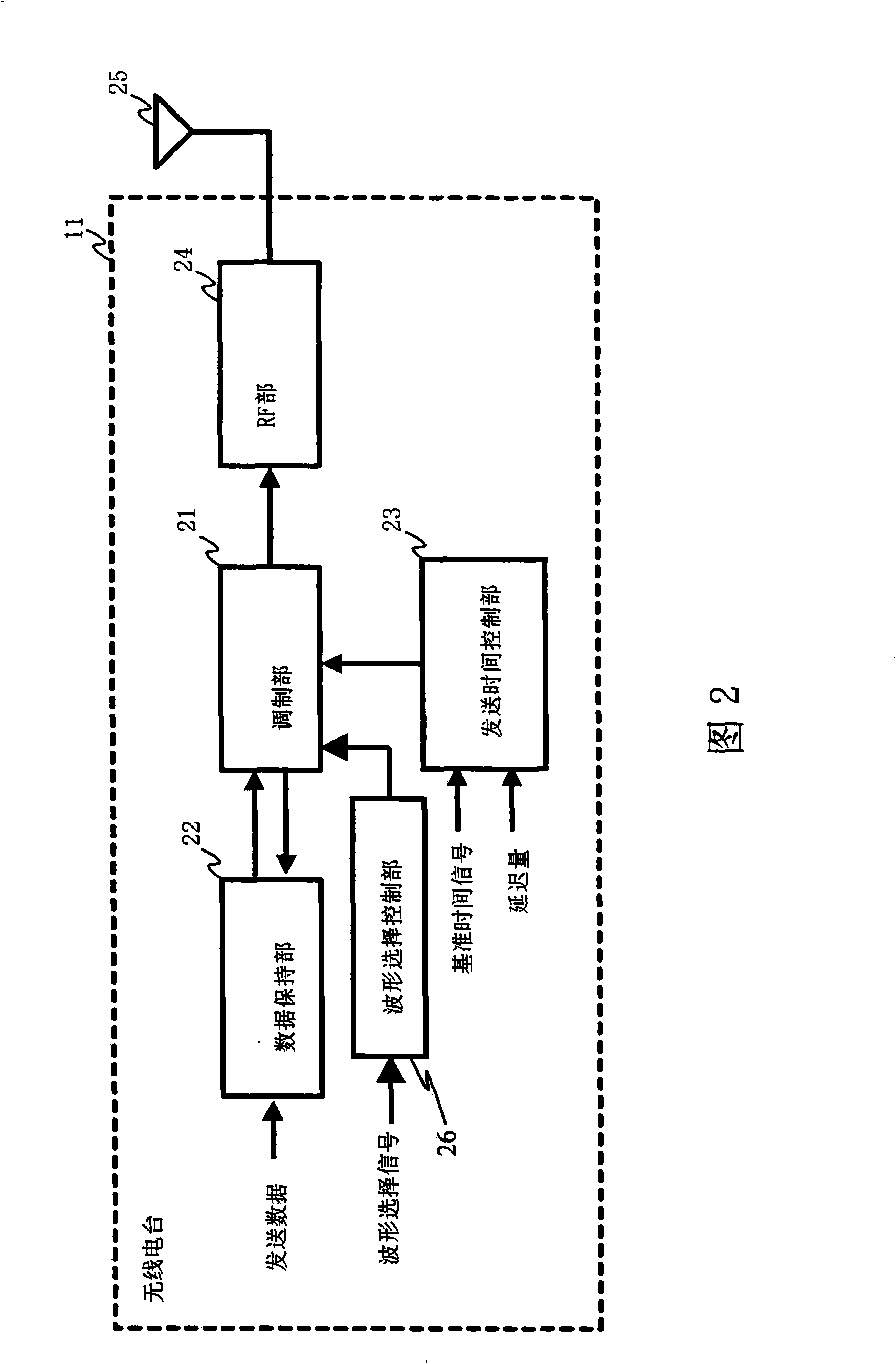
[0118] Each radio station 11 holds transmission data to be transmitted to the receiving station 12 and a reference time signal indicating a time (hereinafter, referred to as a reference time) as a reference for transmitting the transmission data. The tra...

no. 2 approach

[0220] 27 is a diagram showing a configuration of a wireless transmission system according to a second embodiment of the present invention. The wireless transmission system shown in FIG. 27 includes a transmitting station 13 , a plurality of radio stations 14 and a receiving station 12 . The transmitting station 13 and the plurality of radio stations 14 and the plurality of radio stations 14 and the receiving station 12 are wirelessly connected together. The wireless transmission system according to the second embodiment is different from the wireless transmission system according to the above-described first embodiment in that it further includes a transmitting station 13 that transmits a signal to be transmitted to the receiving station 12 to a plurality of radio stations 14 . Hereinafter, the second embodiment will be described focusing on the difference.

[0221] The configuration of the receiving station 13 is obtained by removing the transmission time control unit 23 a...

Embodiment approach 1

[0234] Here, the case of tA=tC=T1 and tB=tD=T2 will be described as an example. The radio stations A1 to D1 transmit signals at either time (T1+G1+Ts) or time (T2+G1+Ts). As in the first embodiment, the radio station A1 and the radio station D1 transmit signals on the symbol waveform W1, and the radio station B1 and the radio station C1 transmit signals on the symbol waveform W2.

[0235] The receiving station 12 receives the signals A1-D1 transmitted from the radio stations A1-D1. Here, it is assumed that the propagation times a2A to a2D between the radio stations A1 to D1 and the receiving station 12 are negligibly small or completely the same, so that it is G2. Therefore, the times at which the receiving station 12 receives the signals A1 to D1 are time (T1+G2+G1+Ts) and time (T2+G2+G1+Ts). And, the difference between the two times is (T2-T1). Therefore, although the symbol waveform is the same, there is an appropriate time difference in the arrival time of the signal be...


PUM


Abstract

A wireless transmission system is provided with a feature in which a combination of a plurality of symbol waveforms brings about the maximum path diversity effect even in the case that the number of the most effective branches is limited to a small number. A transmission timing control unit (23) determines transmission start timing to be timing delayed by a prescribed delay amount from standard timing. A modulating unit (21) uses one from a plurality of symbol waveform candidates to modulate a signal in accordance with a modulation system in which a symbol waveform once demodulated on a receiving side exhibits anti-multiple path characteristics and its phase transition is a changing waveform, and transmits the same at transmission start timing. The prescribed delay amount is such magnitude that the number of receiving timing at which a receiving station (12) receives the signal per symbol waveform is plural and not larger than the number of the maximum effective branches, and that a difference between receiving timing is not less than a prescribed delay resolution and not larger than the upper limit of a prescribed delay.

Description

technical field [0001] The present invention relates to a wireless transmission system and a wireless transmission method for transmitting and receiving signals by a plurality of wireless transmission apparatuses using a transmission method with multipath resistance, and a radio station and a transmitting station used therein. Background technique [0002] In the field of wireless communication, there is a method for improving transmission characteristics, which is to artificially form a plurality of signals by using a modulation-demodulation method that is resistant to multipath, by causing a plurality of transmitting stations to transmit at the same time. path, and the effect of path diversity (or, also referred to as transmit diversity) is obtained by synthesizing a plurality of received arrival waves on the receiving side. [0003] Modulation-demodulation methods that are tolerant to multipath include methods that consider various modulation methods, and methods that use...

Claims


Application Information

Patent Timeline
Patent Type & Authority Applications(China)
IPC IPC(8): H04B7/06H04B7/02H04B7/26
CPCH04B7/022H04B7/026H04W56/0045H04B1/7115
Inventor 高井均宫长健二中原秀树山崎秀聪
Owner PANASONIC CORP
Why Eureka
Try Eureka