Pre-equalisation optical transmitter and pre-equalisation optical fibre transmission system

An optical transmitter and pre-equalization technology, applied in optical transmission systems, optical fiber transmission, transmission systems, etc., can solve problems that have not yet been studied in detail

Inactive Publication Date: 2012-07-18
MITSUBISHI ELECTRIC CORP
View PDF4 Cites 1 Cited by
  • Summary
  • Abstract
  • Description
  • Claims
  • Application Information

AI Technical Summary

Problems solved by technology

However, no detailed study has been conducted on the decentralized management of the case where pre-equalization is applied in an ultra-long-distance optical fiber transmission system

Method used


Image

  • Pre-equalisation optical transmitter and pre-equalisation optical fibre transmission system
  • Pre-equalisation optical transmitter and pre-equalisation optical fibre transmission system
  • Pre-equalisation optical transmitter and pre-equalisation optical fibre transmission system

Examples


Embodiment approach 1

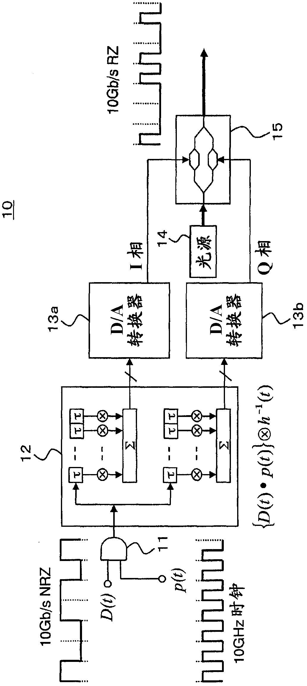
[0031] figure 1 It is a configuration diagram showing the pre-equalized optical transmitter 10 according to Embodiment 1 of the present invention. The pre-equalized optical transmitter 10 transmits an optical signal pre-equalized for the wavelength dispersion of the optical fiber transmission line.

[0032] exist figure 1 Among them, the pre-equalized optical transmitter 10 includes an RZ conversion circuit (RZ conversion unit) 11, a digital filter (pre-equalized data generation unit) 12, D / A converters (D / A conversion unit) 13a, 13b, and a laser light source 14 , and a vector modulator (light modulation unit) 15 .

[0033] Hereinafter, the function of each part of the pre-equalization optical transmitter 10 will be described.

[0034]The RZ conversion circuit 11 is composed of an AND circuit. An input data sequence D(t) of 10 Gb / s NRZ format and a clock p(t) of 10 GHz are input to the RZ conversion circuit 11 to generate an input data sequence of RZ format.

[0035] Here...


PUM


Abstract

Disclosed is a pre-equalisation optical transmitter which is a simple and low-cost structure capable of generating a pre-equalised RZ-type optical signal. Further disclosed is a pre-equalisation optical fibre transmission system which is appropriately managed in a decentralised manner and which uses the pre-equalisation optical transmitter. The transmitter is provided with: an RZ conversion circuit (11), which generates an RZ-type input data sequence on the basis of an NRZ-type input data sequence (D(t)) and a clock signal (p(t)) that is twice the speed of the NRZ-type input data sequence; a digital filter (12), which generates pre-equalised data by performing a convolution calculation between the RZ-type input data sequence and a desired transfer function associated with the wavelength dispersion of an optical fibre transmission path; D / A converters (13a, 13b) which perform D / A conversion on the pre-equalised data and output analogue pre-equalised data; and a vector modulator (15) which modulates the light from a laser light source (14) on the basis of the analogue pre-equalised data and outputs an RZ-type optical signal.

Description

technical field [0001] The present invention relates to a pre-equalized optical transmitter for transmitting an optical signal pre-equalized for wavelength dispersion of an optical fiber transmission path, and a pre-equalized optical fiber transmission system using the pre-equalized optical transmitter. Background technique [0002] In the optical fiber transmission system, it is necessary to compensate for the distortion of the signal waveform caused by the wavelength dispersion of the optical fiber transmission path. As a method of dispersion compensation, a method of using a dispersion compensating optical fiber having a wavelength dispersion of an opposite sign to that of an optical fiber transmission path is widely practiced. In addition, in the recent 40Gb / s or higher high-speed optical fiber transmission system, the signal waveform is easily distorted due to slight changes in the wavelength dispersion caused by temperature, fiber kerf, etc., so it is not to use a disp...

Claims


Application Information

Patent Timeline
Patent Type & Authority Applications(China)
IPC IPC(8): H04B10/02H04B10/04H04B10/06H04B10/14H04B10/18H04B10/26H04B10/28H04B10/2513H04B10/50H04B10/516
CPCH04B10/505H04B10/25137H04B10/5162H04B2210/254
Inventor 水落隆司杉原隆嗣
Owner MITSUBISHI ELECTRIC CORP
Why Eureka
Try Eureka