
Method for heating heat roller and heat roller

A heating method and technology of heating rollers, which are applied in the heating field of heating rollers, can solve problems such as weak thermal conductivity, uneven temperature distribution on the working surface of heating rollers, and influence on the uniformity of heat transfer coefficients, etc., and achieve rapid and uniform temperature distribution , easy to implement in industrialization, and the effect of uniform temperature distribution

Inactive Publication Date: 2010-09-01
TIANJIN POLYTECHNIC UNIV
View PDF1 Cites 0 Cited by
  • Summary
  • Abstract
  • Description
  • Claims
  • Application Information

AI Technical Summary

Problems solved by technology

This heating roller heating method has the following disadvantages: 1. In the initial stage of starting, the temperature distribution on the working surface of the heating roller is uneven, and it takes a long time to gradually make the temperature distribution uniform, and the heating efficiency is not high; 2. Relying on the ring When the heat medium in the cavity transfers heat to the working surface of the heating roller, the heat conduction ability of the heating medium itself and the heat conduction ability between the heating medium and the working surface of the heating roller are weak, and the heat exchange efficiency is insufficient to timely supplement the heat emitted by the heating roller , so it will also cause uneven temperature distribution on the working surface of the heating roller; 3. If there is a space in the annular cavity, the non-condensable gas in the space will seriously affect the heat transfer efficiency, and then affect the uniformity of the heat transfer coefficient; and if the annular cavity The cavity is full of heat medium and there is no space. Since the expansion coefficient of the heat medium is inconsistent with that of the heating roller material, it will affect the stress distribution and shape stability of the heating roller after heating, and then affect the quality of the processed object.
These factors will affect the uniformity of temperature distribution on the working surface of the heating roller, and also restrict the further improvement of the heating roller and its working quality

Method used


Image

  • Method for heating heat roller and heat roller
  • Method for heating heat roller and heat roller
  • Method for heating heat roller and heat roller

Examples


Embodiment 1

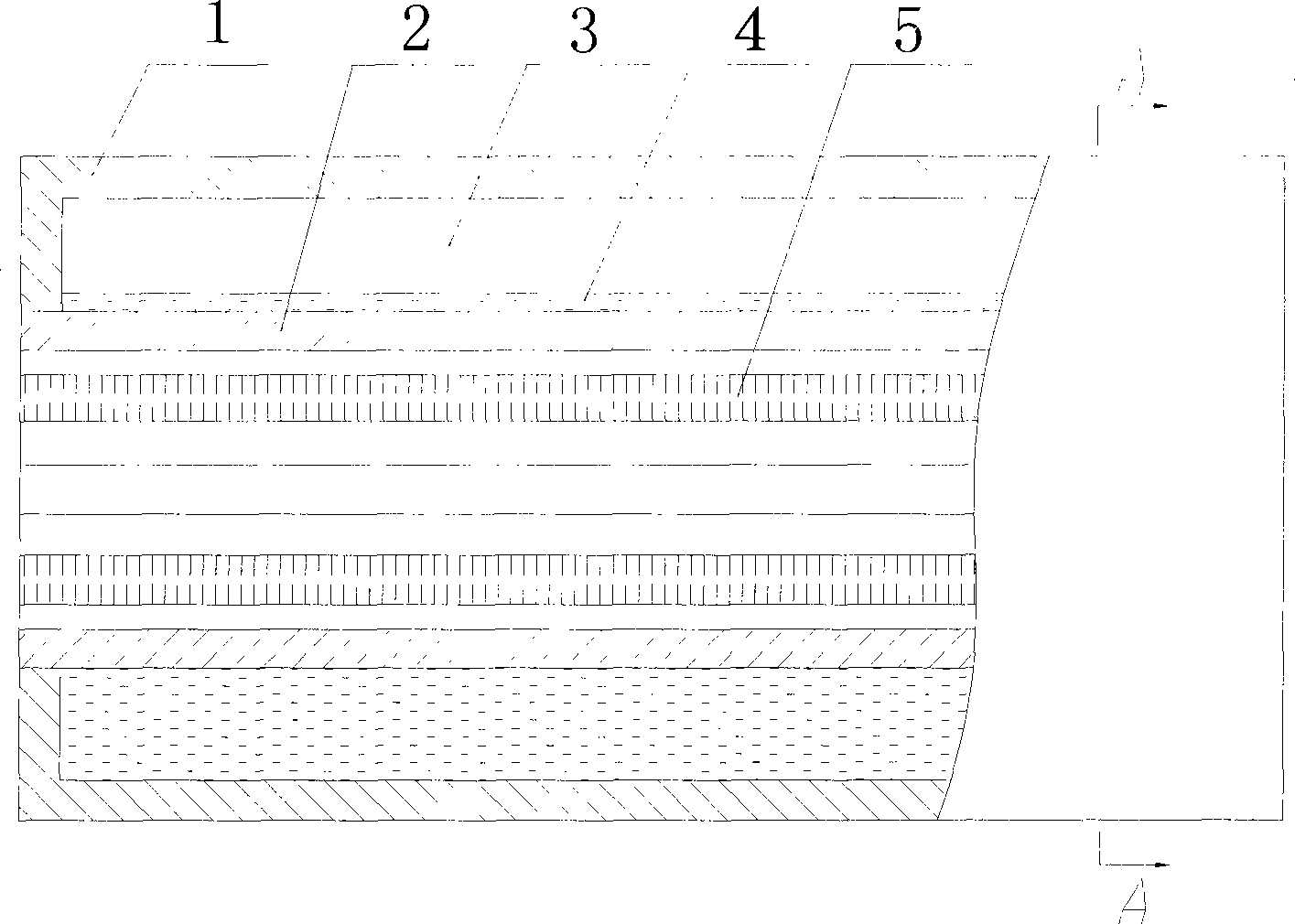
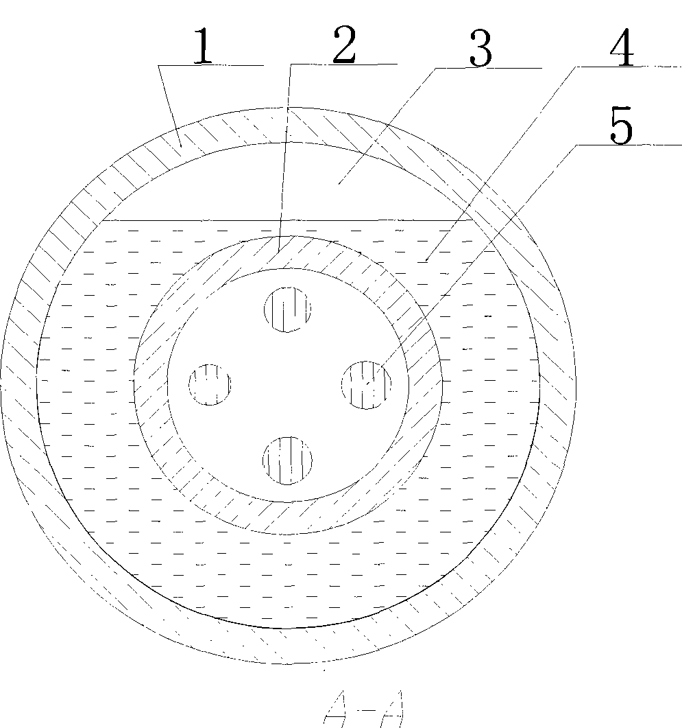
[0038] According to the simple heating roller of the heating method basic requirement design of the present invention (referring to figure 1 , 2 ).

[0039] The heating roller includes an outer roller 1 and a casing 2 installed therein. The annular cavity between the casing 2 and the outer roller 1 is a closed cavity 3, and four sets of heat sources 5 are evenly distributed in the casing 2. The cavity 3 is filled with a heat medium 4, and its characteristic structure is that the annular airtight cavity 3 is a vacuum airtight cavity, and the liquid heat medium 4 that has submerged the upper surface of the casing 2 is sealed in the cavity 3, and the remaining volume is Vacuum state; the liquid heat medium 4 is water; the heat source 5 is an electric heating tube.

Embodiment 2

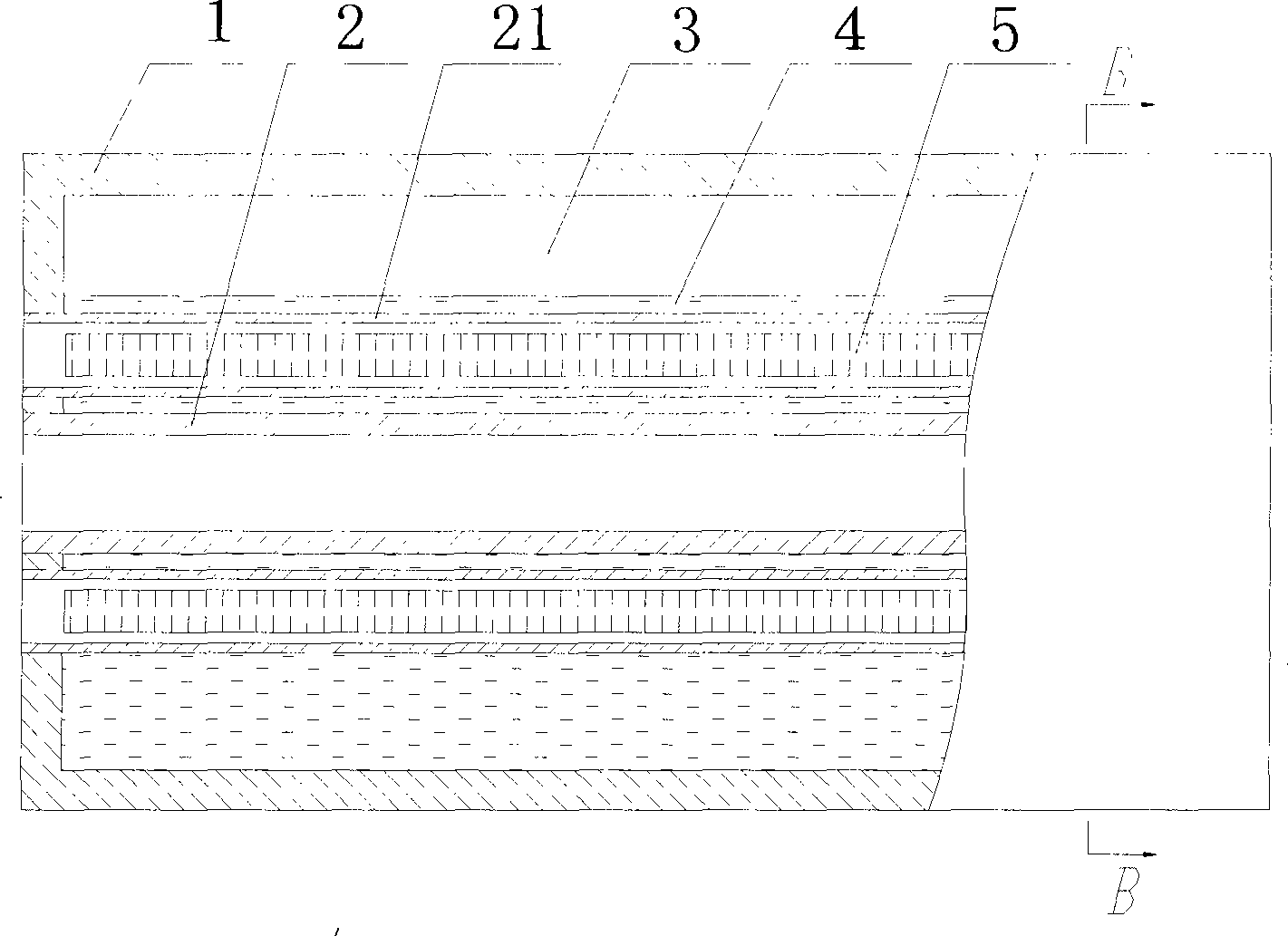
[0041] Another simple heating roller designed according to the basic requirements of the heating method of the present invention (see image 3 , 4 ).

[0042] The characteristic structure of the heating roller is that the diameter of the sleeve 2 is reduced, and the four sets of heat sources 5 are uniformly installed in the annular cavity 3 outside the sleeve 2 and are respectively fitted with heat source sleeves 21 . The rest are the same as embodiment 1.

Embodiment 3

[0044] According to the improvement of heating method of the present invention, a heating roller (referring to) that a heating medium container of design is arranged Figure 5 , 6 ).

[0045] The heating roller includes an outer roller 1 and a casing 2 installed therein. The annular cavity between the casing 2 and the outer roller 1 is a closed cavity 3, which is filled with a liquid heat medium heat transfer oil 41. The casing 2 A group of induction heating devices 51 are installed inside, and its characteristic structure is that the annular airtight cavity 3 is a vacuum airtight cavity, and an open rectangular heat medium container 6 is designed, which is set on the outside of the sleeve 2, and the The liquid heat medium heat transfer oil 4 is filled into the space between the heat medium container 6 and the sleeve pipe 2, so that the heat transfer oil 41 is out of contact with the outer roller 1 of the heating roller, and only the heat that escapes smoothly from the heat m...


PUM


Abstract

The invention relates to a heating method for a heating roller and the heating roller. The heating method is to arrange a sleeve in an outer roller of a heating roller, fill a liquid heating medium in an annular closed cavity formed between the sleeve and the outer roller and arrange a heat source in the sleeve to heat the heating medium by the heat source and heat the outer roller by the heatingmedium. The method is characterized in that: the annular closed cavity is a vacuum closed cavity; the whole space of the cavity consists of a space for holding a certain amount of the liquid heating medium and a vacuum space; the heat source heats the liquid heating medium in the vacuum closed cavity and part of the liquid heating medium undergoes phrase change to generate saturated heating medium vapor to fill in the vacuum space rapidly and heat the outer roller together with the heat source; the certain amount of the liquid heating medium refers to an amount of liquid heating medium meeting the requirement that during heating of the outer roller, the closed cavity is always in a saturated steam and liquid state; the vacuum space refers to a condition that when the temperature of the heating medium is lower than a boiling point at one atmosphere pressure, an absolute pressure in the closed cavity is less than one atmosphere pressure. The heating roller is designed according to the heating method for the heating roller.

Description

technical field [0001] The invention relates to a heating method for a heating roller, specifically a method for heating a heating roller by using heat medium phase change technology and a heating roller prepared by the heating method. The main classification number of the international patent is intended to be Int. ) I. Background technique [0002] Heating rollers have a wide range of application backgrounds in chemical, printing, textile, composite materials and other industries. The heating method of the heating roller currently used can be divided into two categories, one is the method of directly heating the working surface of the heating roller with a heat source; face method. The heat source is oil, steam, electric heating tube, induction and electromagnetic heating, etc. Regardless of the type of heating method, there is a problem of uneven temperature on the working surface of the heating roller. [0003] In order to solve the problem of uneven temperature dist...

Claims


Application Information

Patent Timeline
Patent Type & Authority Patents(China)
IPC IPC(8): B29C43/52B41F16/00B31B1/64B32B37/06B29C63/02D01D1/00B31B50/64
Inventor 吕汉明马崇启傅宏俊嵇境嵇境
Owner TIANJIN POLYTECHNIC UNIV
Learn More