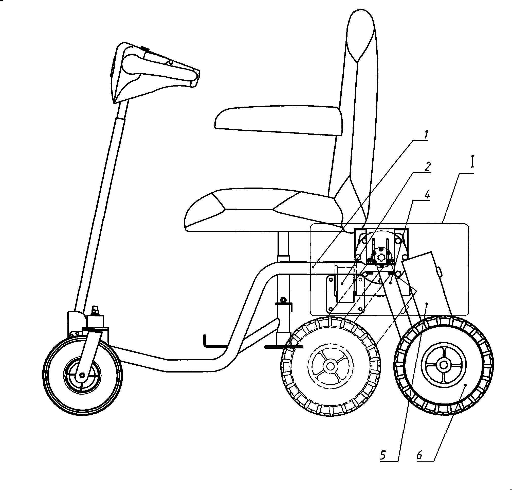
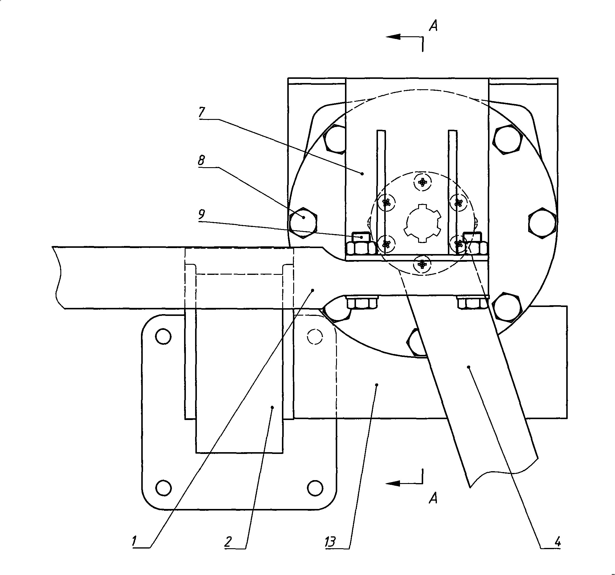
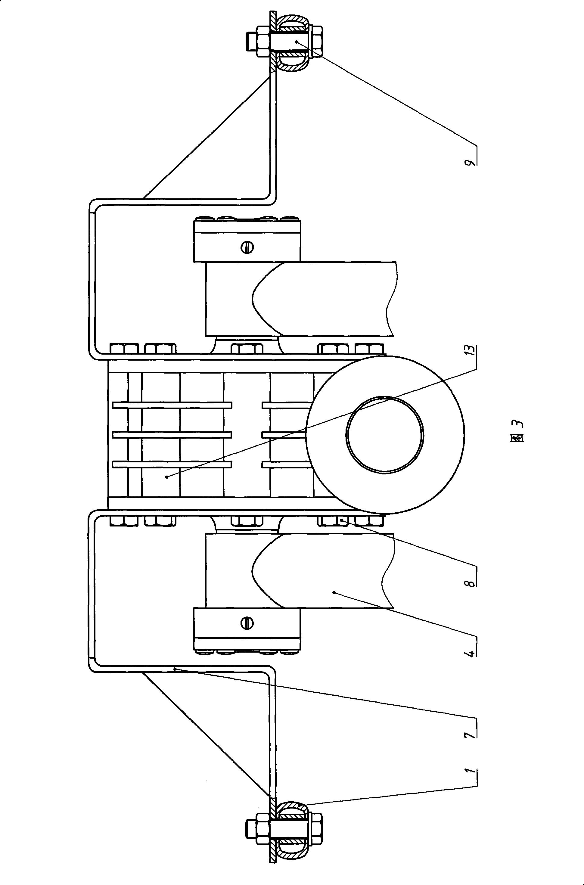
Electric bicycle rear suspension system with worm and gear mechanism for regulating wheelbase
A technology of electric scooter and worm gear, which is applied in axle suspension, bicycle accessories, transportation and packaging, etc. It can solve the problems of passenger discomfort, vibration and shock of worm gear reducer, and influence on the service life of the reducer, and achieve the goal of using The effects of life extension, reliable self-locking safety, and good vibration damping performance
- Summary
- Abstract
- Description
- Claims
- Application Information
AI Technical Summary
Problems solved by technology
Method used
Image
Examples
Embodiment 1
[0021] Embodiment 1 (with reference to Fig. 4,5,7,8,9):
[0022]This example is based on the general description part, and is an example for further improving the vibration reduction and vibration absorption performance of the present invention. In this example, in the end cover hole of the end cover 19, a sleeve 33 sleeved on the output shaft 31 is respectively installed, and the part of the sleeve 33 near the extended end of the output shaft 31 is fixedly sleeved on the output shaft 31 (referring to Fig. 4,7), the other end of this sleeve pipe 33 is sleeved on this output shaft 31 in clearance fit state (referring to Fig. 4,5, 9); There is a state of clearance fit between them - in this embodiment, the middle section of the sleeve 33 and the end cover hole clearance fit part of the end cover 19 is provided with an oil storage tank 3' for storing lubricating oil (refer to Figures 4, 5, 7 ). At both ends of the worm wheel 14, a friction disc 12 fixedly sleeved on the corresp...
Embodiment 2
[0026] This example is an example of the fixed connection structure between the swing arm 4 and the output shaft 31 on the basis of the general description or the first embodiment. In this example, the swing arm 4 is fixedly connected to the output shaft 31 through the swing arm sleeve 20 fixedly connected to the swing arm 4, and simultaneously fixedly connected to the outer end surface of the swing arm sleeve 20 and the end of the output shaft 31. The connection plate 10 on the head is realized; the swing arm sleeve 20 is rotatably sleeved on the outer periphery of the end cover hole hub of the end cover 19, and the connection plate 10 has a sleeve on the end of the output shaft 31 The center hole on the center hole and the end of the output shaft 31 are circumferentially limited by a key. Specifically, in this embodiment (referring to Figs. 3 and 4), the swing arm 4 and the swing arm sleeve 20 are welded as one, and the connection plate 10 is fixed on the end surface of the ...
Embodiment 3
[0027] Embodiment 3 (with reference to Fig. 4,6):
[0028] This example is an example of optimization made on the basis of Example 2. In this example, an anti-off groove is arranged on the outer periphery of the hub portion of the end cap hole of the end cap 19, and an anti-off screw 29 whose front end is inserted into the anti-off groove is installed on the swing arm sleeve 20. Originally, the two friction discs (12 and 12') are fixedly set on the sleeve 33, and one end of the sleeve 33 is fixed on the output shaft 31, and the output shaft 31 at each end is not easy to slide out. . The reliability optimization in this example is only done to improve the reliability of the whole system. Obviously, it is also feasible to adopt other anti-off mechanisms.
PUM
 Abstract
Description
Claims
Application Information
 - R&D
- Intellectual Property
- Life Sciences
- Materials
- Tech Scout
- Unparalleled Data Quality
- Higher Quality Content
- 60% Fewer Hallucinations
Browse by: Latest US Patents, China's latest patents, Technical Efficacy Thesaurus, Application Domain, Technology Topic, Popular Technical Reports.
© 2025 PatSnap. All rights reserved.Legal|Privacy policy|Modern Slavery Act Transparency Statement|Sitemap|About US| Contact US: help@patsnap.com


