Conveyer belt apparatus

A conveyor belt and equipment technology, applied in the field of conveyor belt equipment, to achieve the effect of reducing the number of rollers, reducing maintenance costs, and improving impact deformation

Active Publication Date: 2010-12-29
INNER MONGOLIA YILI INDUSTRIAL GROUP CO LTD
View PDF5 Cites 0 Cited by
  • Summary
  • Abstract
  • Description
  • Claims
  • Application Information

AI Technical Summary

Problems solved by technology

[0009] The technical problem to be solved by the present invention is to provide a conveyor belt device, which can reduce the distance between the products cut by the cutting bow and fall into the tray, and can improve the product quality. Problems with impact deformation caused by conveyor belts falling onto trays

Method used


Image

  • Conveyer belt apparatus
  • Conveyer belt apparatus
  • Conveyer belt apparatus

Examples


Embodiment approach 1

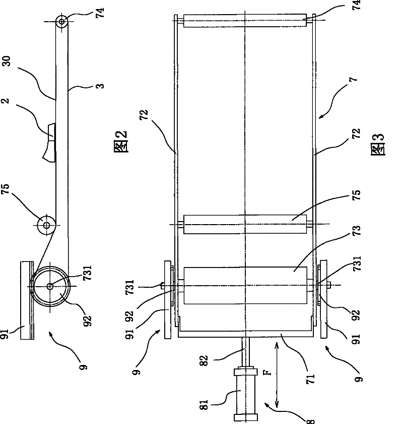
[0029] As shown in Figures 2 and 3, the present invention provides a conveyor belt device, comprising:

[0030] Mobile frame 7, this mobile frame 7 comprises connecting plate 71 and two side plates 72, and the whole is a frame; On the two side plates 72 of this mobile frame 7, a power roller 73 and a static roller 74 are pivotally arranged, and In the present invention, the power roller 73 preferably adopts an electric roller that can be purchased on the market, and the roller skin can be rotated relative to the roller shaft 731 through the magnetic force. Driving the power drum 73 to rotate can simplify the structure of the whole transmission belt equipment. The motor drum is a known part and will not be described in detail; Distance, power drum 73 and static drum 74 are arranged on two side plates 72 inside of mobile frame 7 along the moving direction F of vertical mobile frame 7, and transmission belt 3 is set around power drum 73 and static drum 74; A limit roller 75 can ...

Embodiment approach 2

[0037] As shown in Figure 5, the principle, structure and effect of this embodiment and Embodiment 1 are basically the same, the difference is that: the power drum 73 is not an electric drum that can provide rotational force by itself, but needs to be additionally connected with a rotating mechanism 5 for It provides turning force.

[0038] The power drum 73 is connected with the output shaft of the rotary mechanism 5, and the rotary mechanism 5 is preferably a servo motor, and the output shaft of the servo motor is directly driven and connected with the roller shaft 731 at one end of the power drum 73 through couplings such as a shaft coupling 50. Bracket 51 connects and fixes rotating mechanism 5 on the mobile frame 7 and can move back and forth together with it; Although it is shown in Fig. 5 The type of double-shaft output can be adopted, and the rollers 731 at both ends of the power roller 73 can be driven at the same time, so that the force on the power roller 73 can be ...


PUM


Abstract

The invention provides belt equipment, which comprises a movable stand, a drive mechanism connected to the movable stand and a compensation drive mechanism. A dynamic roller and a static roller which keeps a certain distance from the dynamic roller are pivotally arranged on the movable stand along the direction vertical to the moving direction of the movable stand, a conveyor belt is arranged around the peripheries of the two rollers, and the compensation drive mechanism is linked with the dynamic roller and provides speed increment for the conveyor belt along the direction opposite to the moving direction of the movable stand driven by the drive mechanism. The belt equipment has very simple structure, low maintenance cost and greatly reduced energy loss of power transmission, and can lead the diameter of the static roller at the front end of the conveyor belt to be very small, reduce the distance of the product cut off by a cutter to a tray and improve the problem of impact deformation of the product when falling on the tray from the conveyor belt.

Description

technical field [0001] The invention relates to a conveyor belt device, in particular to a conveyor belt device used in food processing and packaging fields such as cold drinks. Background technique [0002] At present, in the process of food processing and packaging such as cold drinks, most of the conveyor belt equipment for horizontal extrusion products that are often used are shown in Figure 1, including: frame 1, and the horizontal extrusion nozzle 2 is located immediately above the frame 1 At the frame 1, the first moving drum 11, the second moving drum 12 connected to the first moving drum 11 through the rod 10, the first static drum 13, the tension drum 14, the power drum 15, the second static drum Drums 16, the transmission belt 3 is wrapped around these drums; the motor 4 is fixed on the bottom of the frame 1, and its power is transmitted to the power drum 15 through the drive belt 41; the second moving drum 12 and the piston rod 61 of a cylinder 6 connect. [0...

Claims


Application Information

Patent Timeline
Patent Type & Authority Patents(China)
IPC IPC(8): B65G15/00B65G23/04B65G23/24
Inventor 温红瑞杜志强薛乃民任敬刚
Owner INNER MONGOLIA YILI INDUSTRIAL GROUP CO LTD
Why Eureka
Try Eureka