Four-range multiplication system far-field monitoring device and collimating method thereof

A technology of amplification system and monitoring device, applied in the direction of instruments, optics, optical components, etc., can solve the problems of limited precision, high cost, and difficult application of four-pass amplification system

Inactive Publication Date: 2010-06-09
SHANGHAI INST OF OPTICS & FINE MECHANICS CHINESE ACAD OF SCI
View PDF1 Cites 0 Cited by
  • Summary
  • Abstract
  • Description
  • Claims
  • Application Information

AI Technical Summary

Problems solved by technology

This method is not only costly but also has limited accuracy, and it is difficult to apply in a four-pass amplification system with a relatively complex structure.

Method used


Image

  • Four-range multiplication system far-field monitoring device and collimating method thereof
  • Four-range multiplication system far-field monitoring device and collimating method thereof
  • Four-range multiplication system far-field monitoring device and collimating method thereof

Examples


Embodiment Construction

[0026] The present invention will be further described below in conjunction with the embodiments and drawings, but the protection scope of the present invention should not be limited by this.

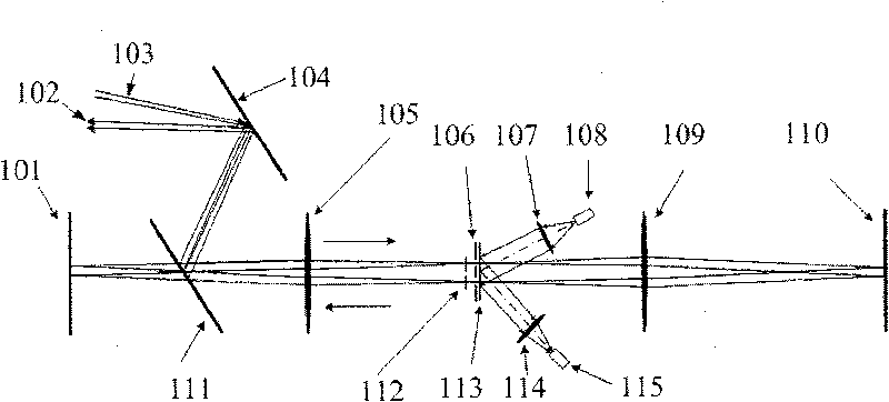
[0027] See first figure 1 , figure 1 It is a schematic diagram of the optical path of the far-field monitoring device of the four-way amplification system of the present invention. It can be seen from the figure that the composition of the far-field monitoring device of the four-way amplification system of the present invention includes:

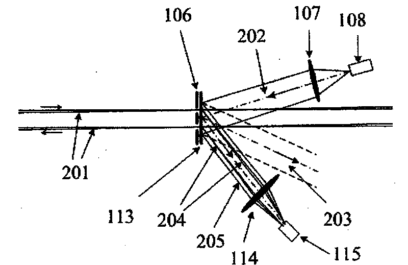
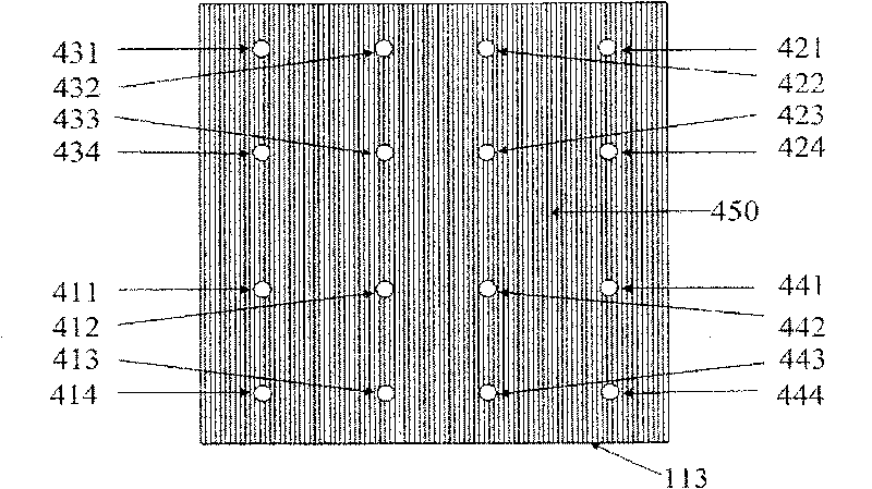
[0028] A four-way magnification system consisting of a first mirror 101, a polarizing mirror 111, a first lens 105, a half-wave plate 112, a filter aperture 106, a second lens 109, and a second mirror 110 in sequence. The filter orifice plate 106 is symmetrically distributed with the first filter orifice 301, the second filter orifice 302, the third filter orifice 303 and the fourth filter orifice 304, which are closely attached to the filter orifice plat...


PUM


Abstract

The invention relates to a distant field monitoring device for a quadruple pass amplifying system of a high power laser aid and a collimating method thereof. The structure of the device comprises: a sampling raster is inserted cling to the filtering aperture plate behind the filtering aperture plate; the illuminating bundle formed by a lighting diode and a collimating lens which are arranged outside the main laser beam of the quadruple pass amplifying system lights the sampling raster in certain angle; an imaging lens and a CCD probing device are arranged along the first stage diffraction light direction, the probing surface of the CCD probing device is arranged on the image plane of the imaging lens and the output terminal of the CCD probing device is connected with a computer. The devicesolves the difficult problems of the distant field sampling and collimating adjustment of the quadruple pass amplifying system, and has the advantages of simple device and high precision.

Description

Technical field [0001] The invention relates to a high-power laser device, in particular to a four-pass amplification system far-field monitoring device and a collimation method for the high-power laser device. Background technique [0002] The schematic diagram of the optical path of the four-pass amplification system of the high-power laser device is as follows Figure 4 As shown, a four-way magnification system consisting of a first mirror 101, a polarizing mirror 111, a first lens 105, a half-wave plate 112, a filter aperture 106, a second lens 109, and a second mirror 110 in sequence, A resonant cavity constituted by a first mirror 101 and a second mirror 110. The resonant cavity has a spatial filter constituted by a first lens 105, a half-wave plate 112, a filter aperture 106 and a second lens 109, Figure 4 The schematic plan view of the filter hole plate 106 is as follows: Figure 5 Shown. The center of the filter orifice plate 106 is located on the optical axis of the four...

Claims


Application Information

Patent Timeline
Patent Type & Authority Patents(China)
IPC IPC(8): G02B27/30G02F1/35G02B27/46
Inventor 高妍琦刘代中朱宝强林尊琪刘晓凤
Owner SHANGHAI INST OF OPTICS & FINE MECHANICS CHINESE ACAD OF SCI
Why Eureka
Try Eureka