A stepped collimator structure for direct-write vacuum evaporation system

A technology of vacuum evaporation and collimation tube, applied in vacuum evaporation plating, metal material coating process, coating and other directions, can solve the problems of shortening the service life of mask holes, particle scattering, blocking of mask holes, etc. Small scattering, improved vacuum, reduced processing effect

Active Publication Date: 2020-07-31
TSINGHUA UNIV
View PDF1 Cites 0 Cited by
  • Summary
  • Abstract
  • Description
  • Claims
  • Application Information

AI Technical Summary

Problems solved by technology

[0003] The existing vacuum evaporation device that does not include a shifting sample stage is to directly attach the photoresist to the sample substrate, so as to realize the function of processing a specific sample shape, so there will be no technical problems such as gaseous target beam scattering, However, for a vacuum evaporation device with a shifting sample stage, there may be a micron-level gap between the mask and the substrate, and the mask hole scale (<1 μm), is prone to particle scattering problems”; at the same time, the direction of motion The non-collimated gaseous target beam will also cause the mask hole to be blocked (the evaporated gaseous target particle flow hits the inner wall of the mask hole and condenses, causing the mask hole to be blocked), which shortens the service life of the mask hole

Method used


Image

  • A stepped collimator structure for direct-write vacuum evaporation system
  • A stepped collimator structure for direct-write vacuum evaporation system
  • A stepped collimator structure for direct-write vacuum evaporation system

Examples


Embodiment Construction

[0026] Embodiments of the present invention are described in detail below, examples of which are shown in the drawings, wherein the same or similar reference numerals designate the same or similar elements or elements having the same or similar functions throughout. The embodiments described below by referring to the figures are exemplary and are intended to explain the present invention and should not be construed as limiting the present invention.

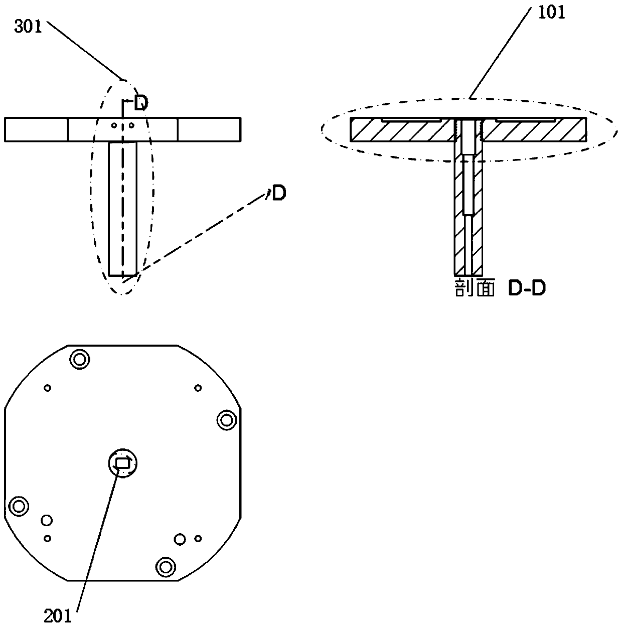
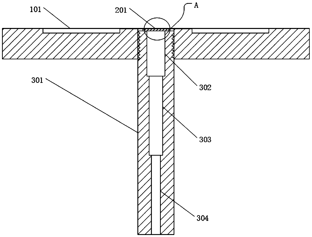
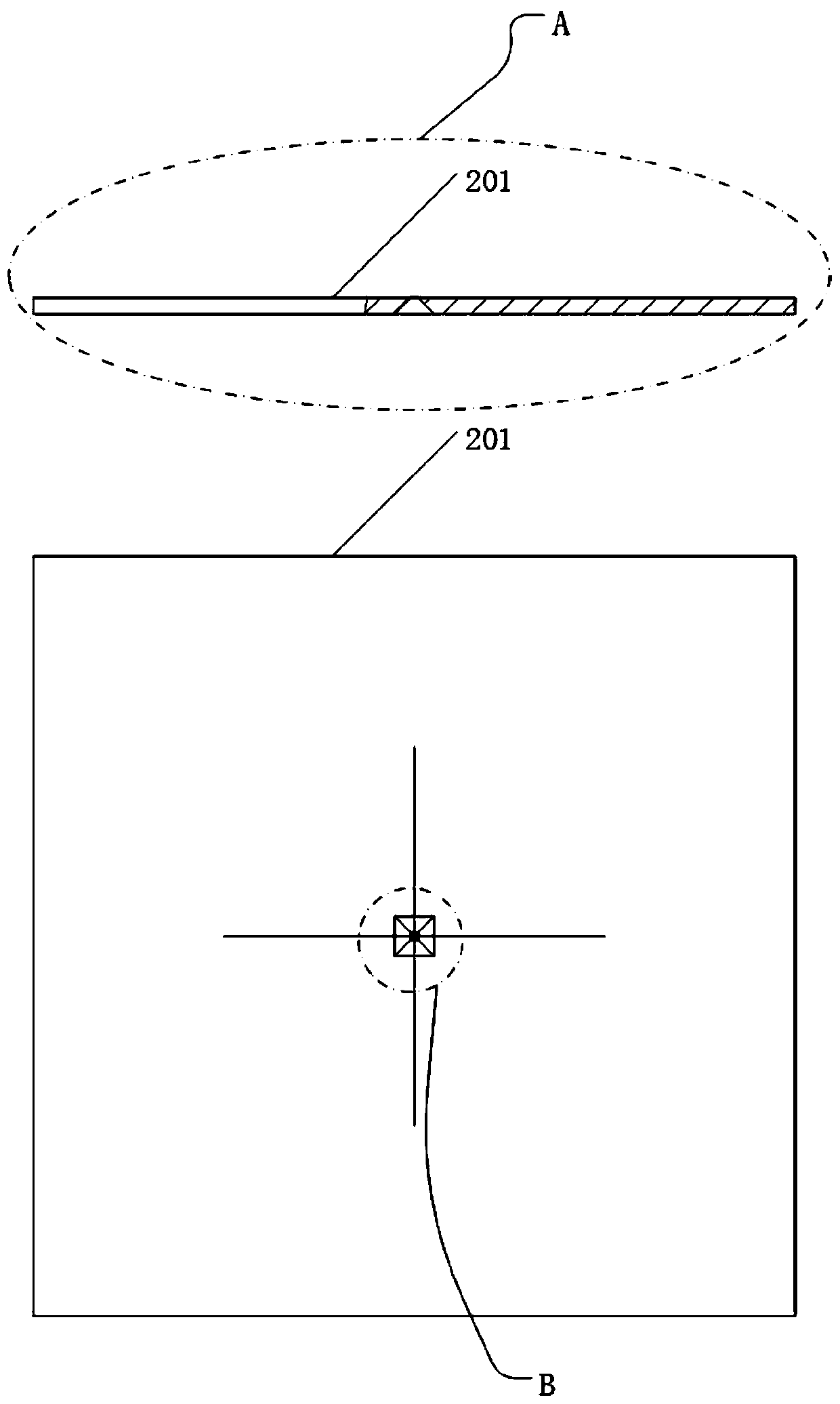
[0027] Refer below Figure 1-Figure 4 A novel stepped collimator structure according to an embodiment of the present invention is described. Such as Figure 1-Figure 4 As shown, the stepped collimator structure according to the embodiment of the present invention includes: a base 101; a mask sheet 201, the mask sheet 201 is located at the center of the upper surface of the base 101, and its upper surface and the base The upper surface of 101 is of the same height and is fixed by glue bonding; the collimation tube 301 is located...


PUM


Abstract

The invention discloses a novel stepped collimated pipe structure applied to a direct writing type vacuum evaporation system for preventing mask hole blockage and particle scattering. The stepped collimated pipe structure comprises a base, a mask piece, a collimated pipe, a first particle reflection stop step, a second particle reflection stop step and a collimated hole. The first particle reflection stop step is located on the upper portion inside the collimated pipe and connected with the upper surface of the collimated pipe and the upper surface of the second particle reflection stop step,the second particle reflection stop step is located in the middle inside the collimated pipe and connected with the lower surface of the first particle reflection stop step and the upper surface of the collimated hole, the collimated hole is located on the lower portion inside the collimated pipe and connected with the lower surface of the second particle reflection stop step and the lower surfaceof the collimated pipe. The direct writing type vacuum evaporation system has the advantages that the structure is compact, the machining speed is high, the mask service life is long, machining feature edge is clear, particle scattering can be avoided, materials are saved, and the machining purity is high.

Description

technical field [0001] The invention relates to a novel stepped collimation tube structure used in a direct-writing vacuum evaporation system for preventing mask hole blockage and particle scattering. Background technique [0002] The invention patent "A Direct-Writing Vacuum Evaporation System and Its Method" (Patent No.: WO2015100730A1) proposes a direct-writing vacuum evaporation system. On the basis of maintaining the structure of the sample chamber of the existing vacuum evaporation device, the invention introduces The nano-shift positions the sample stage and the mask mechanism, so that the evaporated high-purity gas-phase target material is transformed into a gas-phase target material beam with a nanoscale size, which is directly deposited on the substrate, thereby realizing the preparation of free patterns. [0003] The existing vacuum evaporation device that does not include a shifting sample stage is to directly attach the photoresist to the sample substrate, so as...

Claims


Application Information

Patent Timeline
Patent Type & Authority Patents(China)
IPC IPC(8): C23C14/04C23C14/50C23C14/24
CPCC23C14/042C23C14/24C23C14/50
Inventor 张震柳铮闫鹏鲁帅帅
Owner TSINGHUA UNIV
Why Eureka
Try Eureka