
Host controller device and data transfer control method

A technology of data transmission and main controller, which is applied in the direction of electrical digital data processing, data exchange through path configuration, instruments, etc., can solve the problems of reducing data transmission efficiency, not facilitating data transmission, unsatisfactory, etc., and achieve improvement The effect of data transfer efficiency

Inactive Publication Date: 2009-04-15
NEC ELECTRONICS CORP
View PDF0 Cites 0 Cited by
  • Summary
  • Abstract
  • Description
  • Claims
  • Application Information

AI Technical Summary

Problems solved by technology

[0006] As a result, there is a problem in the host controller device for USB, since it is necessary to successively read a cycle of endpoint information including endpoint information that does not facilitate data transfer, it will be unsatisfactory. Reduce data transfer efficiency

Method used


Image

  • Host controller device and data transfer control method
  • Host controller device and data transfer control method
  • Host controller device and data transfer control method

Examples


no. 1 example

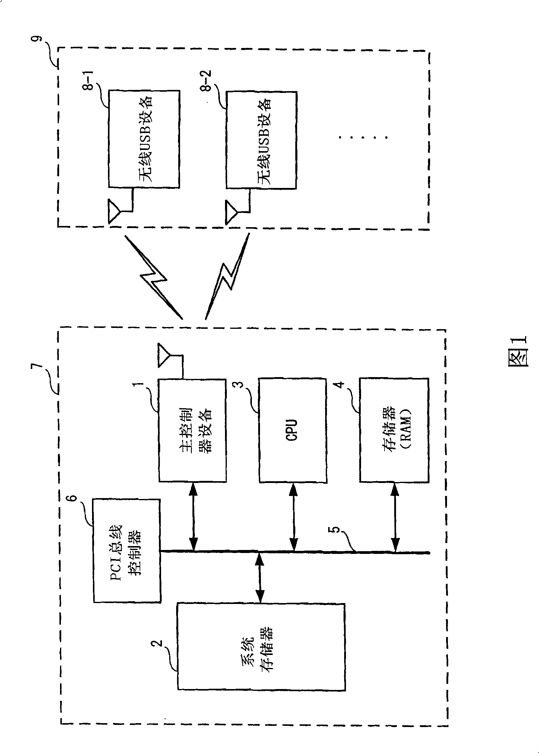
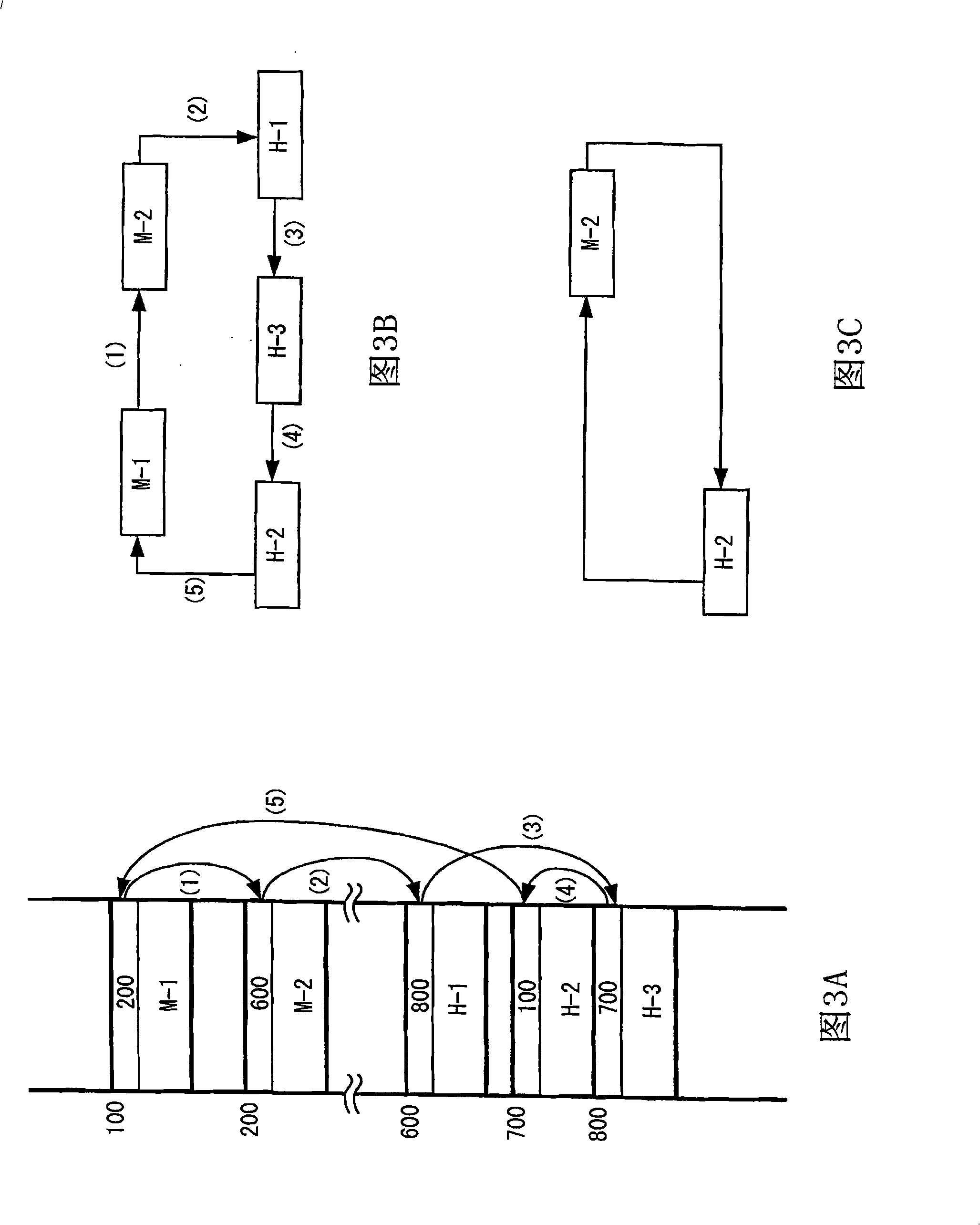
[0031] As a first embodiment, a case will be described below in which an address in the system memory 2 holding valid endpoint information is stored in a storage area within the main controller.

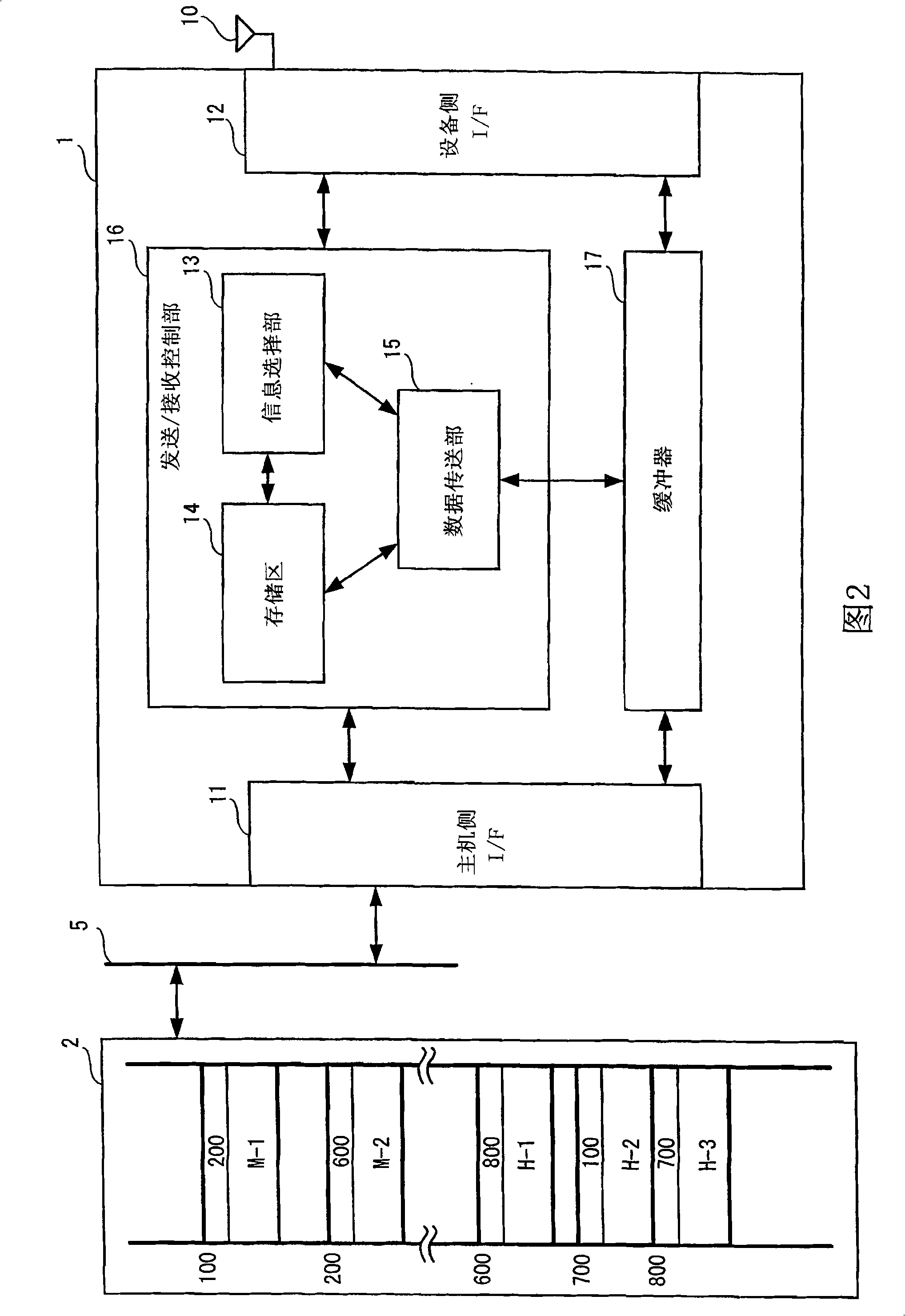
[0032] FIG. 2 is a block diagram showing an example of the structure of a main controller device according to one embodiment of the present invention. Furthermore, FIG. 2 also shows an example of the system memory 2 . The main controller device 1 includes a host-side interface (hereinafter referred to as "host-side I / F") 11, a device-side interface (hereinafter referred to as "device-side I / F"), a transmission / reception control section 16, and Buffer 17.

[0033] The host-side I / F 11 sends data to and receives data from the system memory 2 and other components in the host device 7 through the PCI bus 5 . The device side I / F 12 transmits data to and receives data from the slave device 9 by wireless communication.

[0034] The transmission / reception control section 16 controls data ...

no. 2 example

[0053] As a second embodiment, a case will be described below in which endpoint information causing data transfer is selected from a plurality of endpoint information located in the system memory, and the selected is stored in the storage area 14 within the main controller device 1. The endpoint information of is used as valid endpoint information. The main controller device 1 has a structure similar to that shown in FIG. 2 . In the following description, differences in operation of the transmission / reception control section 16 from that in the first embodiment will be mainly explained.

[0054] The information selection unit 13 generally follows Figure 4 The shown flowchart operates except that in step S15 it stores the valid endpoint information itself in the system memory 2 in addition to the address corresponding to the valid endpoint information. Other operations are the same as those of the first embodiment. E.g, Figure 7 An example of a result of analyzing and stor...


PUM


Abstract

Data transfer efficiency has been unsatisfactorily decreased in host controller devices for USBs because of the fact that they must read out a loop of endpoint information including endpoint information that do not contribute to data transfer in a successive manner. In accordance with one embodiment of the present invention, a host controller device installed in a host device having a system memory 2 to communicate with a USB device includes an information select portion 13 to select endpoint information requesting data transfer by analyzing a plurality of endpoint information held in the system memory 2, a storage area 14 to store at least one address in system memory 2 identifying the selected endpoint information, and a data transfer portion 15 to carry out the requested data transfer based on the endpoint information identified by the at least one address in system memory 2 stored in the storage area 14.

Description

technical field [0001] The present invention relates to a master controller for realizing data transmission by using a USB (Universal Serial Bus) device. Background technique [0002] Although the technical specification of the USB protocol is established on the assumption that the USB (Universal Serial Bus) is used in a wired environment, a wireless USB technology capable of making the USB useless of a connecting wire has been developed in recent years. For example, data transfer using a wireless USB device through wireless communication has been realized by equipping a host device with a driver for controlling data transfer with a wired USB device, and a host controller device for wireless communication. In USB, data transfer is performed based on endpoint information. In such cases, the endpoint information is located in the system memory of the master device. Therefore, the host controller device must successfully read and parse the endpoint information located in syst...

Claims


Application Information

Patent Timeline
Patent Type & Authority Applications(China)
IPC IPC(8): H04L29/06H04L12/40
CPCG06F13/4295
Inventor 狩谷广士
Owner NEC ELECTRONICS CORP
Learn More