Quieter of electrical heating cooker

Inactive Publication Date: 2009-04-22
东莞市逸迅通信科技有限公司
View PDF0 Cites 10 Cited by
  • Summary
  • Abstract
  • Description
  • Claims
  • Application Information

AI Technical Summary

Problems solved by technology

After using these electric pressure heating cookers to cook the food, it needs to relieve the pressure. The existing pressure relief structure is composed of a straight pressure relief pipe and a gravity valve on it. The pressure relief pipe connects the high pressure gas inside the pressure cooker and the external atmospheric pressure. When the gravity valve is lifted, the pressure relief pipe directly releases the high-pressure gas in the pot to the external atmospheric pressure. Because the high-pressure gas is directly ejected, the airflow has a large pulsation and a fast flow rate to generate sound waves of certain frequencies. These pressure relief produces The noise is particularly harsh, causing discomfort to users

Method used


Image

  • Quieter of electrical heating cooker
  • Quieter of electrical heating cooker
  • Quieter of electrical heating cooker

Examples


Embodiment Construction

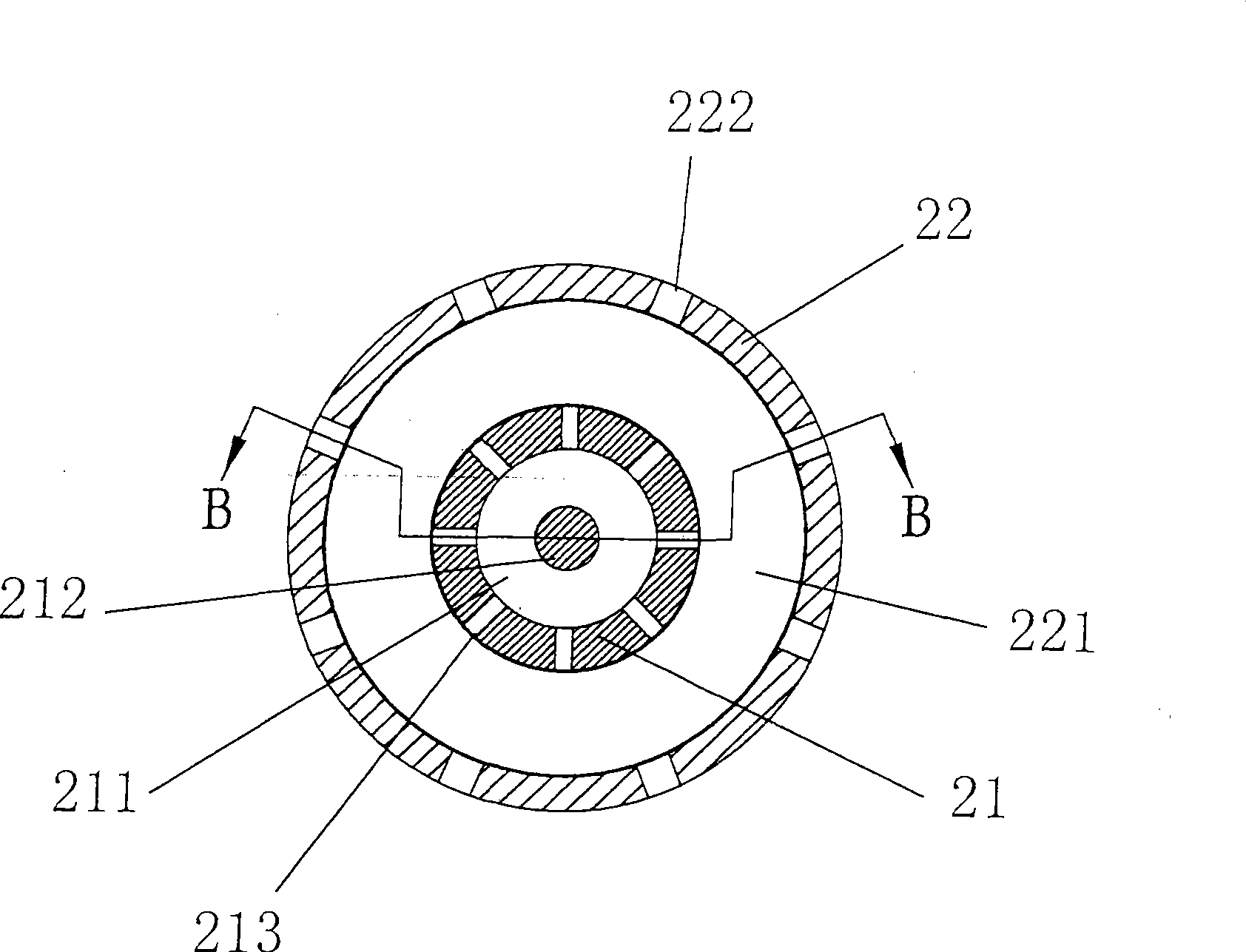
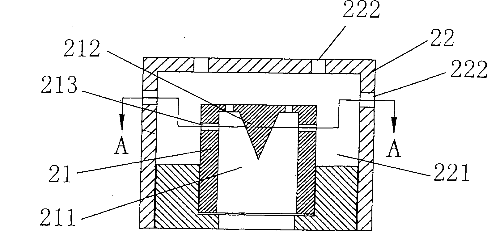
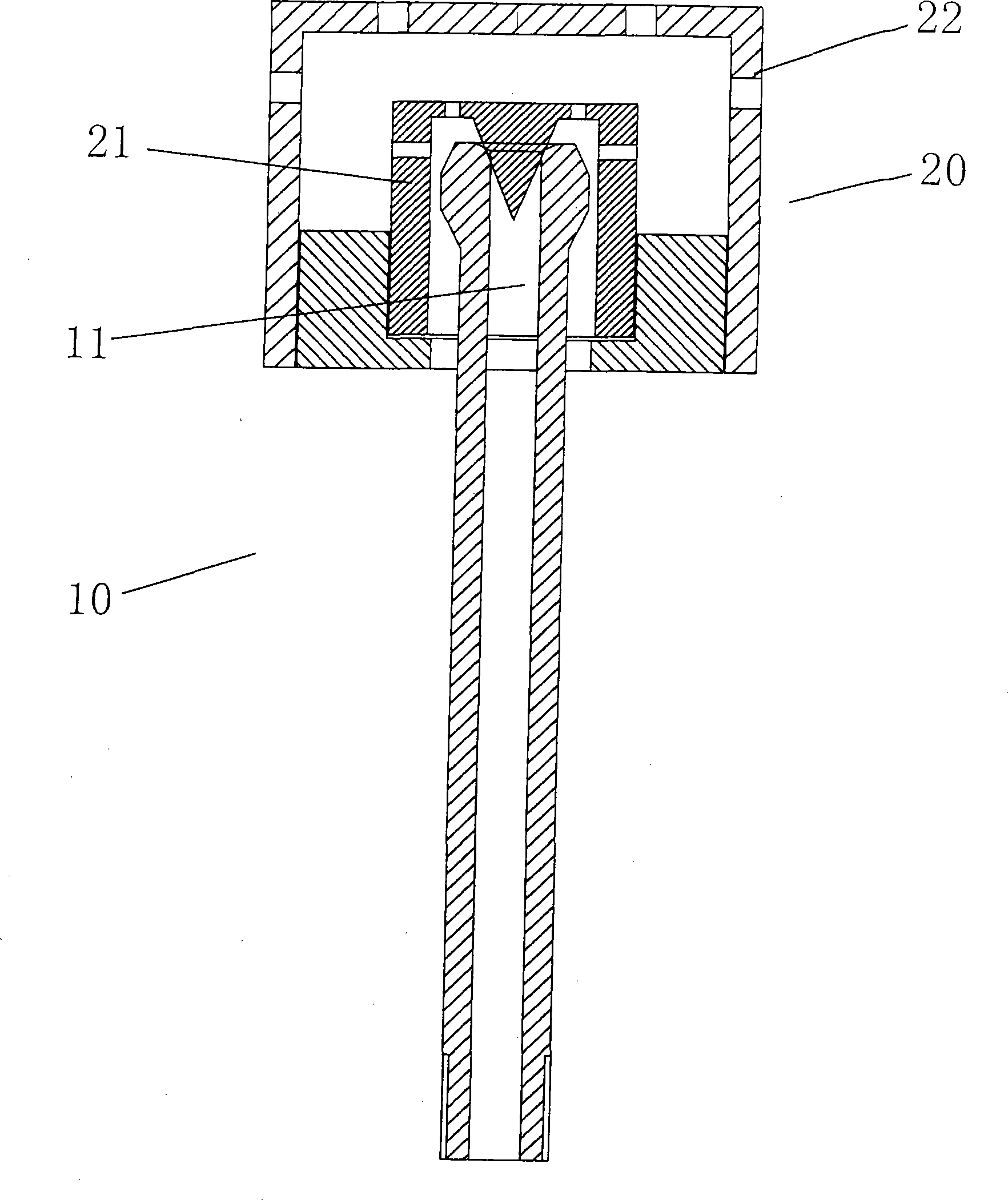
[0014] Such as Figure 1-4 As shown, the present invention includes an electric heating cooker body, an exhaust valve core 10 is installed on the electric heating cooker body, and a gravity valve 20 is provided at the position of the air outlet 11 of the exhaust valve core 10. The gravity valve 20 includes The exhaust valve body 21 and the exhaust valve cover 22. One end of the exhaust valve body 21 is provided with a plug cavity 211 into which the air outlet 11 of the exhaust valve core 10 is inserted, and the exhaust valve body 21 is provided with an exhaust The valve plug 212 matched with the outlet 11 of the spool 10; the exhaust valve cover 22 covers the outside of the exhaust valve body 21 and forms a cavity 221 with the outer surface of the exhaust valve body 21; in the exhaust valve body 21 There are several vent holes 213 on the top, several vent holes 222 on the exhaust valve cover 22, the vent holes 213 on the exhaust valve body 21 and the vent holes on the exhaust valve...


PUM


Abstract

The invention relates to a muffle device applied in an electric heating cooker, which comprises an electric heating cooker body provided with a gas exhaust valve core. A weight valve is arranged on the position of a gas outlet of the gas exhaust valve core. The weight valve is formed by connecting a gas exhaust valve body and a gas exhaust valve cover. The gas exhaust valve body is cylindrical, one end of the gas exhaust valve body is provided with an inserting cavity for inserting the gas outlet of the gas exhaust valve core, and the gas exhaust valve body is provided with a valve plug matched with a gas outlet on the gas exhaust valve cover; the gas exhaust valve cover covers the outside of the gas exhaust valve body and forms a cavity with the outer surface of the gas exhaust valve body; and the gas exhaust valve body is provided with a plurality of vent holes, the gas exhaust valve cover is provided with a plurality of gas outlets, and the vent holes on the gas exhaust valve body are staggered with the gas outlets on the gas exhaust valve cover. Therefore, air flow reflects back and forth through the inner wall of the cavity of the gas exhaust valve body, so that sound wave of certain frequency, which is transmitted along the cavity body wall, emits back at mutation position in the sound source direction, and the muffle aim is achieved.

Description

Technical field [0001] The invention relates to the technical field of electric heating cookers, and particularly refers to a muffler device used in electric heating cookers. Background technique [0002] At present, various electric heating cookers have been widely used, and some of the electric heating cookers use high pressure for cooking, which can cook food faster, such as electric pressure cookers. After using these electric pressure heating cookers to cook the food, the pressure needs to be relieved. The existing pressure relief structure is composed of a straight pressure relief pipe and a gravity valve on it. The pressure relief pipe connects the high pressure gas in the pressure cooker and the external atmospheric pressure. When the gravity valve is lifted, the pressure relief tube directly releases the high-pressure gas in the pot into the external atmospheric pressure. Because the high-pressure gas is directly ejected, the pulsation of the airflow is very large, and t...

Claims


Application Information

Patent Timeline
Patent Type & Authority Applications(China)
IPC IPC(8): A47J27/09
Inventor 肖端午刘有根龚邵贵
Owner 东莞市逸迅通信科技有限公司
Why Eureka
Try Eureka