Switch reluctance motor

A technology of switched reluctance motors and motor bases, applied in the direction of electrical components, electromechanical devices, electric components, etc., can solve the problems of high noise of switched reluctance motors, achieve small torque ripple, enhance structural strength, and facilitate errors Effect

Active Publication Date: 2013-01-23
DONGFENG MOTOR CORP HUBEI
View PDF11 Cites 7 Cited by
  • Summary
  • Abstract
  • Description
  • Claims
  • Application Information

AI Technical Summary

Problems solved by technology

[0006] The purpose of the present invention is to overcome the defects and deficiencies of the high noise of the switched reluctance motor in the prior art, and to provide a switched reluctance motor with a compact structure and low noise

Method used


Image

  • Switch reluctance motor
  • Switch reluctance motor
  • Switch reluctance motor

Examples


Embodiment Construction

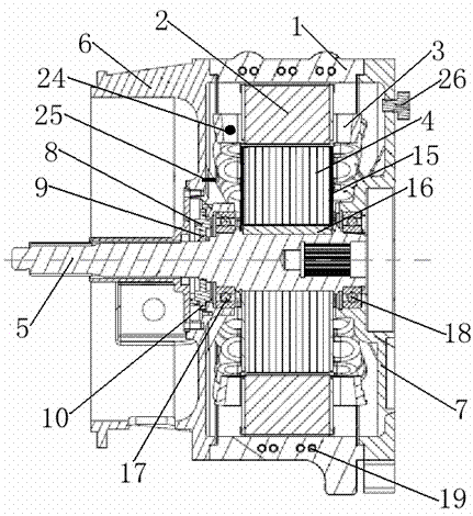
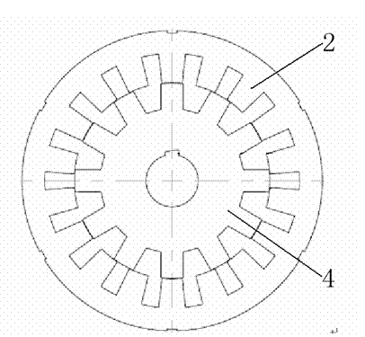
[0030] Below in conjunction with accompanying drawing description and specific embodiment, the present invention will be described in further detail:

[0031] see Figure 1-Figure 2 , a switched reluctance motor, comprising a motor frame 1, a stator 2 is arranged on the motor frame 1, a stator winding 3 is wound on the stator 2, a rotor 4 is housed in the stator 2, and the rotor 4 The rotor shaft 5 is fixed inside, the motor base 1 is provided with a front end cover 6 and a rear end cover 7, and the stator 2, rotor 4 and rotor shaft 5 are located in the closed space surrounded by the front end cover 6 and the rear end cover 7 Inside, the two sides of the rotor 4 are provided with pressure plates 15, the rotor 4 and the rotor shaft 5 are connected by a flat key 16, one end of the rotor shaft 5 is provided with a rectangular external spline, and the other end of the rotor shaft 5 Involute inner splines are provided, a winding temperature sensor 24 is provided inside the stator ...


PUM


Abstract

The invention discloses a switch reluctance motor comprising a motor base, wherein a stator is arranged on the motor base; a stator winding is wound on the stator; a rotor is arranged in the stator; a rotor shaft is fixed in the rotor; the motor base is provided with a front end cover and a rear end cover; the stator, the rotor and the rotor shaft are located in a sealed space defined by the front end cover and the rear end cover; a rotary transformer is arranged between the front end cover and the rotor; the transformer rotor of the rotary transformer is fixedly connected with the rotor shaft; the transformer stator of the rotary transformer is fixedly connected with t he front end cover; the stator winding is a three-phase concentrated winding; the stator and the rotor are in a doubly salient structure; eighteen magnetic poles are uniformly distributed on the stator; twelve magnetic poles are uniformly distributed on the rotor; and magnetic poles on the stator and the rotor are in a trapezoid gear structure. With the advantages of simple structure, reliable work, steady operation, small torque pulsation and low noise, the motor is conveniently applied on automobiles.

Description

technical field [0001] The invention relates to the technical field of motors, in particular to a switched reluctance motor. Background technique [0002] The speed control motor is a kind of motor that changes the speed of the motor by changing the number of stages, voltage, current, frequency, etc. of the motor, so that the motor can achieve higher performance. Including frequency conversion speed regulation motor, DC speed regulation motor. Since the DC motor has the characteristics of low speed and high torque, it cannot be replaced by the AC motor, so the DC speed control motor has been widely used in the fields of industrial DC motor speed control, industrial conveyor belt speed control, lighting adjustment, computer power cooling, DC fans, etc. application. [0003] China Patent Authorization Announcement No. CN 202395551U, the utility model patent of the authorized announcement date on August 22, 2012 discloses an electric excitation brushless starter and generator...

Claims


Application Information

Patent Timeline
Patent Type & Authority Applications(China)
IPC IPC(8): H02K29/03H02K11/00H02K5/20H02K11/20H02K11/25
Inventor 普刚张大双周垚叶新伟郑翔斌
Owner DONGFENG MOTOR CORP HUBEI
Why Eureka
Try Eureka