Supercharge Your Innovation With Domain-Expert AI Agents!

Driving device of automatic tool changer

A technology of automatic tool changer and driving device, which is applied in the direction of positioning device, metal processing machine parts, clamping, etc., and can solve the problems that the operator is difficult to maintain the motor, and lead to the front side of the fixed frame, etc.

Active Publication Date: 2010-09-08
SUMITOMO HEAVY IND LTD
View PDF1 Cites 0 Cited by
  • Summary
  • Abstract
  • Description
  • Claims
  • Application Information

AI Technical Summary

Problems solved by technology

[0008] However, in such a conventional drive device for an automatic tool changer, the motor is mounted on the rear side of the fixed frame of the automatic tool changer, so it is very difficult for an operator to maintain the motor.
However, in order to facilitate this maintenance, for example, when the motor is arranged on the front side (relative to the operation panel) for the operator, it will be necessary to send the detection signal of the cable for the power supply of the motor or the encoder. The new problem that the used cable is routed to the front side of the fixed frame

Method used


Image

  • Driving device of automatic tool changer
  • Driving device of automatic tool changer
  • Driving device of automatic tool changer

Examples


Embodiment Construction

[0043] Hereinafter, an example of the embodiment of the present invention will be described in detail with reference to the drawings.

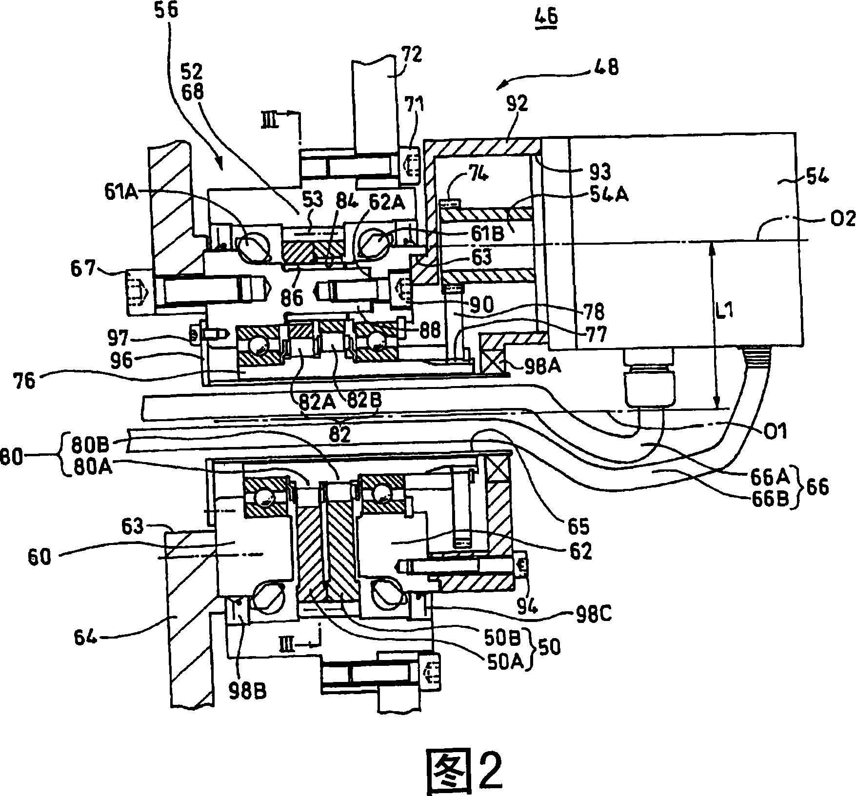
[0044] FIG. 1 is a longitudinal sectional view showing an example of an embodiment of a driving device of an automatic tool change mechanism according to the present invention, and FIG. 2 is an enlarged view of an essential part of FIG. 1 . In addition, FIG. 3 is a sectional view taken along arrow III-III line of FIG. 2 .

[0045] The description will start from the outline with emphasis on FIG. 1 . The driving device 48 of the automatic tool changer mechanism 46 includes a speed reducer 56 that decelerates and outputs the rotation of the motor 54 as relative rotation between the external gear 50 and the internal gear 52 . The external gear 50 oscillates and meshes internally with the internal gear 52 .

[0046] On both axial sides of the external gear 50 are provided first and second brackets 60 , 62 which are synchronized with the rotation...


PUM


Abstract

The invention provides a driving device of automatic tool changing mechanism capable of easily winding cable of electrometer regardless of the configuration of electromotor and decelerator relative to fixing frame of the automatic tool changing mechanism. The driving device (48) automatic tool changing mechanism (46) comprises a decelerator (56) transmitting the deceleration output by the relative rotation between an external gear (50) and an inner gear (52), wherein the two sides of the external gear (50) are provided with a first and a second brackets (60, 62), an electromotor (52) is mounted when the axial centers of the first and second brackets (60, 62) are deviated, such that a hollow part (65) running through the center of semi-diameter of the decelerator (56) is formed, cable (66)for the electromotor (54) is inserted in the hollow part (65), and a driving sprocket (72) for driving the joint-less chain (70) of the automatic tool changing mechanism (46) is fixed on a shell (68) integrated with the inner gear (52).

Description

technical field [0001] The invention relates to a driving device of an automatic tool changing mechanism. Background technique [0002] An automatic tool changing mechanism such as a machining center takes out a required tool from a tool magazine that holds many tools on the outer periphery, and automatically performs an exchange operation with the tool held on the spindle. As a drive device for the above-mentioned tool magazine of such an automatic tool change mechanism, for example, a device shown in FIGS. 4 and 5 is known (Patent Document 1). [0003] The rotation of the motor 3 is decelerated by the speed reducer 5 and transmitted as the rotation of the drive sprocket 7 . The drive sprocket 7 rotates the endless chain C. On the other hand, in the tool magazine B of the automatic tool change mechanism 9, a plurality of tool holders P for storing tools are connected by the endless chain C at equal intervals. When the endless chain C is rotated by the rotation of the dri...

Claims


Application Information

Patent Timeline
Patent Type & Authority Patents(China)
IPC IPC(8): B23Q3/155
CPCB23Q3/15526
Inventor 鹤身洋芳贺卓
Owner SUMITOMO HEAVY IND LTD
Features
  • R&D
  • Intellectual Property
  • Life Sciences
  • Materials
  • Tech Scout
  • Unparalleled Data Quality
  • Higher Quality Content
  • 60% Fewer Hallucinations
Learn More