Cylinder with devices for containing lubricants

A technology for lubricants and cylinders, applied in the directions of cylinders, cylinder heads, engine components, etc., can solve problems such as high cost

Inactive Publication Date: 2009-04-22
WAERTSILAE SCHWEIZ AG
View PDF4 Cites 8 Cited by
  • Summary
  • Abstract
  • Description
  • Claims
  • Application Information

AI Technical Summary

Problems solved by technology

Besides the cost, which is considerable for large diesel engines, the consumption of lubricants also represents an environmental burden

Method used


Image

  • Cylinder with devices for containing lubricants
  • Cylinder with devices for containing lubricants
  • Cylinder with devices for containing lubricants

Examples


Embodiment Construction

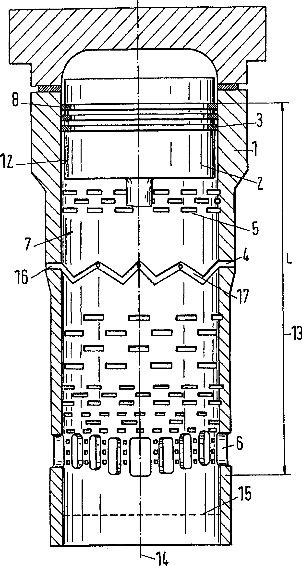
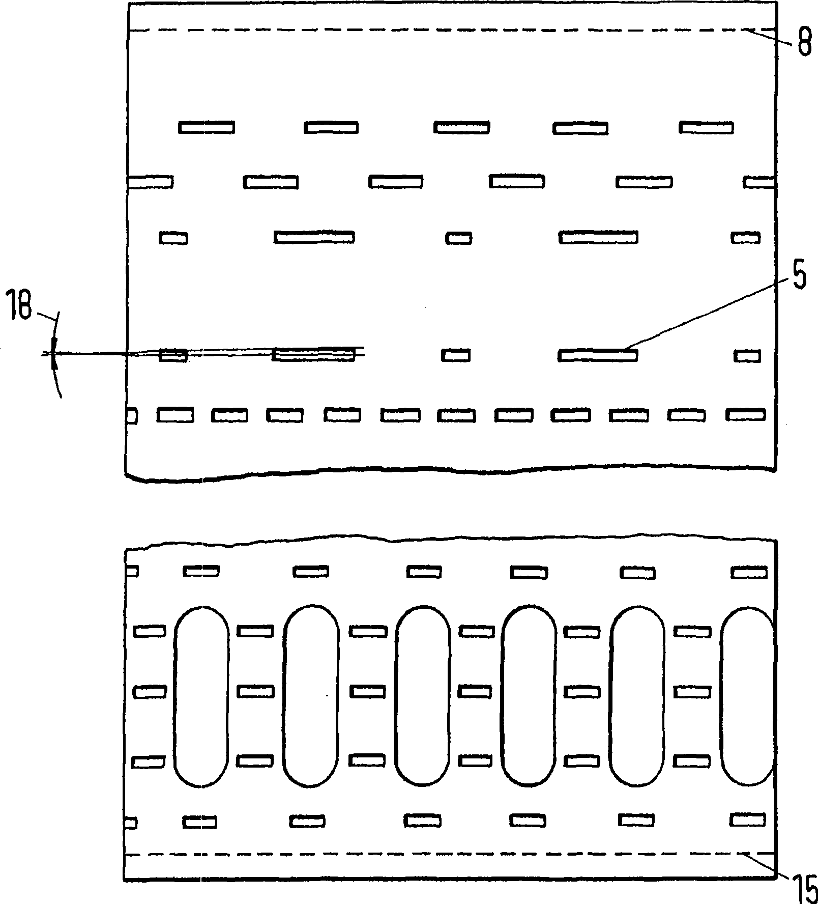
[0022] figure 1 A section through a cylinder 1 provided in a piston engine is shown. The piston engine is a two-stroke or four-stroke engine, especially a large diesel engine. This large diesel engine is generally equipped with a cylinder, and the inner diameter of this cylinder is mostly greater than 190mm. Typical diameters are between 250 and 1000mm. A piston reciprocates inside the cylinder and is connected to a rotatable drive shaft via a connecting rod. This reciprocating movement of the piston occurs between top dead center and bottom dead center. figure 1 The piston is shown in the top dead center position. If a section perpendicular to the axis of the cylinder is placed through the top dead center of the uppermost piston ring, the plane will intersect the inner wall of the cylinder along a line which is hereinafter referred to as the top dead center zone 8. With the vertical arrangement of the cylinders, the top dead center zone 8 forms the uppermost boundary of...


PUM


Abstract

The invention relates to a cylinder with a device used to receive lubricant. A cylinder (1) comprises a device (5) used to receive lubricant. The cylinder comprises a sliding surface (7) for a piston (2) and the sliding surface has a dead point area (8) and a row of purifying grooves (6) disposed on the cylinder. The sliding surface (7) is provided with a plurality of gouge recesses (5) with length (9), width (10) and depth (11) which is over 0.4mm. The gouge recesses are disposed below an annular area of a cylinder surface (12). The annular area has length which is 15% of the length (13) of the sliding surface (7) when measured from the dead point area (8) thereon.

Description

technical field [0001] The invention relates to a cylinder for a piston engine comprising means for receiving lubricant. Background technique [0002] In large two-stroke or four-stroke engines, the distribution of the lubricant proves to be very critical due to the need to wet large surfaces. Lubricant enters the inner space of the cylinder through a limited number of feed holes provided at the periphery of the cylinder. In order to distribute the liquid lubricant evenly on the inner wall of the cylinder, peripherally extending grooves are provided, such as, for example, shown in FR1174532. However, it has been shown that during long-term operation of the engine these grooves are subject to significant wear, especially in the highly loaded part of the cylinder, from the top dead center of the uppermost piston ring to the bottom dead center of the piston. The point direction can extend up to about 15% of the distance. Due to the constant high pressure in this region, whic...

Claims


Application Information

Patent Timeline
Patent Type & Authority Applications(China)
IPC IPC(8): F02F1/18F02F1/20F16J10/04
CPCF02F1/20F02F1/18F02F1/22
Inventor H·森登
Owner WAERTSILAE SCHWEIZ AG
Why Eureka
Try Eureka