Apparatus for checking electronic type current mutual inductor

A technology of current transformer and calibration device, which is applied in the direction of measuring device, instrument, measuring electric variable, etc. Difficulty in acquisition and other problems, to overcome the long-term accuracy is not high enough, improve the working life, reduce the effect of white noise and DC components

Active Publication Date: 2009-04-22
NARI TECH CO LTD
View PDF0 Cites 55 Cited by
  • Summary
  • Abstract
  • Description
  • Claims
  • Application Information

AI Technical Summary

Problems solved by technology

At present, the domestic electronic current transformer calibration device is mainly realized by the (1) method; in the (2) method, an electronic current transformer with high enough long-term accuracy is required, and it is difficult to obtain such equipment. No patents or literature reports
[0004] The transformer calibration device using the above method (1) can obtain high calibration accu

Method used


Image

  • Apparatus for checking electronic type current mutual inductor
  • Apparatus for checking electronic type current mutual inductor
  • Apparatus for checking electronic type current mutual inductor

Examples


Embodiment Construction

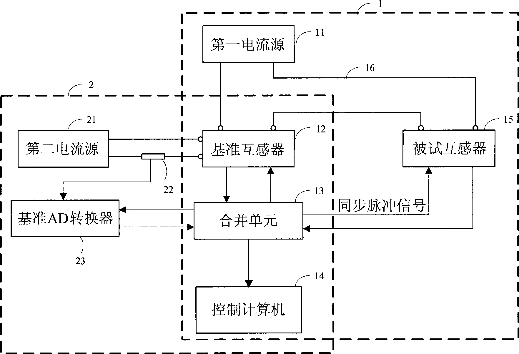
[0022] Such as figure 1 As shown, it is a schematic block diagram of the composition of the calibration device of the present invention, including a calibration system 1 and a self-calibration system 2, the calibration system 1 realizes the calibration function of the tested transformer 15, and the self-calibration system 2 realizes the calibration of the reference transformer 12 online self-calibration functions.

[0023] The calibration system 1 is composed of a first current source 11 , a reference transformer 12 , a merging unit 13 , a control computer 14 , and a transformer 15 under test. The connecting wire passes through the reference transformer 12 and the tested transformer 15 at the same time, so that the current signal A1 generated by the first current source 11 is simultaneously sensed by both. The reference transformer 12 and the tested transformer 15 are all connected to the merging unit 13, and the merging unit 13 outputs a synchronous pulse signal (5kHz) to th...


PUM


Abstract

The invention discloses an electronic current transformer calibrating device. Two current sources respectively transmit current signals A1 and A2, wherein, the A1 is bigger than the A2 and has different frequency from the A2. A reference transformer senses the A1 and the A2 which is amplified by N folds simultaneously, and a tested transformer senses the A1. A merging unit transmits a synchronization pulse signal to the reference transformer, the tested transformer and an AD converter simultaneously, obtains digital quantities of current sampling values of the reference transformer and the tested transformer and the digital quantity of the voltage value at the two ends of a sampling resistor which is obtained by conversion with a reference AD converter at the falling edge of the synchronization pulse signal, and synthesizes the digital quantities into a data frame and sends the data frame to a control computer. The control computer compares the current signal which is obtained by sensing the A1 by the reference transformer with the current signal output by the tested transformer, calibrates the scale difference and the angular difference of the tested transformer, compares the current signal which is obtained by sensing NA2 by the reference transformer with the current signal which is obtained by converting the output voltage from the reference AD converter, and performs self calibration on the reference transformer.

Description

technical field [0001] The invention belongs to the field of power system automation and relates to a transformer calibration device. Background technique [0002] Current transformer (abbreviated as CT) is an important equipment for electric energy metering and relay protection in the power system. Its long-term stability, reliability and safety are closely related to the safe and stable operation of the power system. There are two main types of current transformers currently in use: one is electromagnetic current transformers, and the other is electronic current transformers. Electromagnetic current transformers are based on the principle of electromagnetic induction and have been widely used in power systems. However, they have shortcomings such as magnetic saturation, ferromagnetic resonance, small dynamic range, inability to measure DC, and difficulties in insulation design, which have been difficult to meet the needs of power system development. need. Electronic curr...

Claims


Application Information

Patent Timeline
IPC IPC(8): G01R35/02
Inventor 王巍张志鑫刘东伟李永兵谭金权王利清李淮海
Owner NARI TECH CO LTD
Why Eureka
Try Eureka