A self-calibration method and device for binocular ranging on a moving platform

A binocular distance measurement and self-calibration technology, which is applied in the directions of measuring devices, measuring distance, line-of-sight measurement, etc., can solve problems such as inability to accurately mark system errors and cumbersome processes, so as to facilitate engineering implementation, improve measurement accuracy, and realize The effect of self-calibration

Active Publication Date: 2021-09-07
SHANGHAI AEROSPACE CONTROL TECH INST
View PDF3 Cites 0 Cited by
  • Summary
  • Abstract
  • Description
  • Claims
  • Application Information

AI Technical Summary

Problems solved by technology

[0005] The technical problem solved by the present invention is: to overcome the disadvantages of calibration on a dedicated turntable in order to compensate for installation errors in the prior art, but the process is cumbersome, and other system errors cannot be accurately marked, and a dual- Visual range self-calibration method and device

Method used


Image

  • A self-calibration method and device for binocular ranging on a moving platform
  • A self-calibration method and device for binocular ranging on a moving platform
  • A self-calibration method and device for binocular ranging on a moving platform

Examples


Embodiment 1

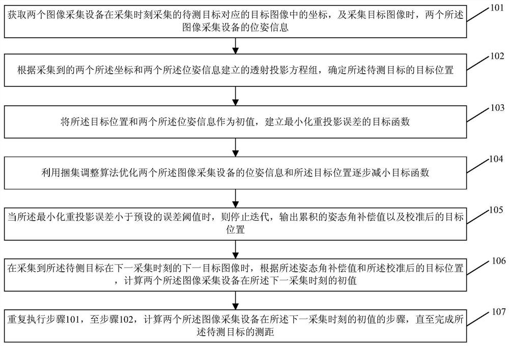
[0056] refer to figure 1 , which shows a flow chart of the steps of a self-calibration method for binocular ranging on a moving platform provided by an embodiment of the present invention, as shown in figure 1 As shown, the binocular ranging self-calibration method of the moving platform may specifically include the following steps:

[0057] Step 101: Obtain the coordinates in the target image corresponding to the target to be measured collected by the two image acquisition devices at the acquisition time, and the pose information of the two image acquisition devices when the target image is acquired;

[0058] Step 102: Determine the target position of the target to be measured according to the transmission projection equation set established by the two collected coordinates and the two pose information;

[0059] Step 103: Using the target position and the two pose information as initial values, establish an objective function that minimizes the reprojection error;

[0060] St...

Embodiment 2

[0094] refer to Figure 5 , which shows a schematic structural diagram of a binocular ranging self-calibration device for a moving platform provided by an embodiment of the present invention, as shown in Figure 5 As shown, the binocular ranging self-calibration device of the moving platform can specifically include the following modules:

[0095] The coordinate pose acquisition module 501 is used to acquire the coordinates in the target image corresponding to the target to be measured collected by the two image acquisition devices at the acquisition time, and the pose information of the two image acquisition devices when acquiring the target image;

[0096] A target position determining module 502, configured to determine the target position of the target to be measured according to the transmission projection equation set established by the two collected coordinates and the two pose information;

[0097] An objective function establishment module 503, configured to use the ...


PUM


Abstract

The invention provides a binocular ranging self-calibration method and device for a moving platform. The method includes: obtaining the coordinates in the target image corresponding to the target to be measured collected by the two image acquisition devices, and the pose information of the two image acquisition devices; the transmission projection equation established according to the two coordinates and the two pose information group, determine the target position of the target to be measured; establish the objective function that minimizes the reprojection error; optimize the pose information and target position of the two image acquisition devices to gradually reduce the objective function; when the minimum reprojection error is less than the preset error When the threshold is reached, the iteration is stopped, and the attitude angle compensation value and the calibrated target position are output; when the next target image of the side target at the next acquisition time is collected, according to the attitude angle compensation value and the calibrated target position, calculate two The initial value of an image acquisition device at the next acquisition moment; repeat the above steps until the distance measurement of the target to be measured is completed. The invention can improve the measuring precision of the ranging system.

Description

technical field [0001] The invention relates to the technical field of visual triangulation calibration, in particular to a self-calibration method and device for binocular ranging on a moving platform. Background technique [0002] For application scenarios with high real-time requirements, long-distance targets and possible moving targets, the traditional fixed-platform binocular ranging method is no longer applicable. [0003] The binocular distance measurement method of the moving platform is installed with navigation equipment, which can obtain the poses of the two cameras in real time to obtain the internal and external parameters of the camera. Therefore, it is no longer necessary to obtain the internal and external parameters of the camera through calibration methods like the fixed platform binocular distance measurement system. parameters (the relative poses of the two cameras cannot be changed during the measurement process), the relative poses of the two cameras c...

Claims


Application Information

Patent Timeline
Patent Type & Authority Patents(China)
IPC IPC(8): G01C3/18G01C25/00G06T7/70G06T7/80
CPCG01C3/18G01C25/00G06T7/70G06T7/80
Inventor 武宏程许东欢朱婧文陈光山吴昊
Owner SHANGHAI AEROSPACE CONTROL TECH INST
Why Eureka
Try Eureka