Apparatus and method to compensate a driving current of a light emitting diode

A technology of light-emitting diodes and driving currents, which can be used in lighting devices, electric lamp circuit layouts, cathode ray tube indicators, etc., and can solve problems such as increasing the total cost.

Inactive Publication Date: 2009-04-22
HIMAX TECH LTD
View PDF0 Cites 17 Cited by
  • Summary
  • Abstract
  • Description
  • Claims
  • Application Information

AI Technical Summary

Problems solved by technology

However, in this known technique, an additional photodetector is required, which increases the overall cost

Method used


Image

  • Apparatus and method to compensate a driving current of a light emitting diode
  • Apparatus and method to compensate a driving current of a light emitting diode
  • Apparatus and method to compensate a driving current of a light emitting diode

Examples


Embodiment Construction

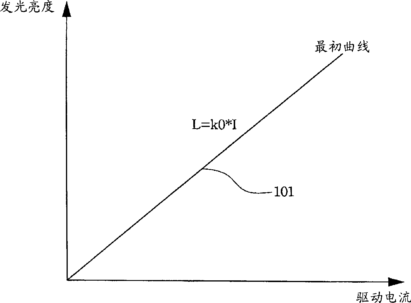
[0021] figure 1 Shown is a graph of luminous brightness and driving current, which is used to describe the relationship between the luminous brightness of an LED and the driving current. Among them, different light-emitting devices have different light-emitting brightness and driving current curves. The horizontal axis represents the driving current, and the vertical axis represents the luminance of light emission. According to curve 101, the luminous brightness is proportional to the driving current. In other words, the greater the driving current, the stronger the luminous brightness. The relationship between the two can be expressed by the following formula:

[0022] L=K×I

[0023] Wherein L represents the brightness, I represents the driving current, K is the slope of the curve and the coefficient for obtaining a luminous brightness under a driving current.

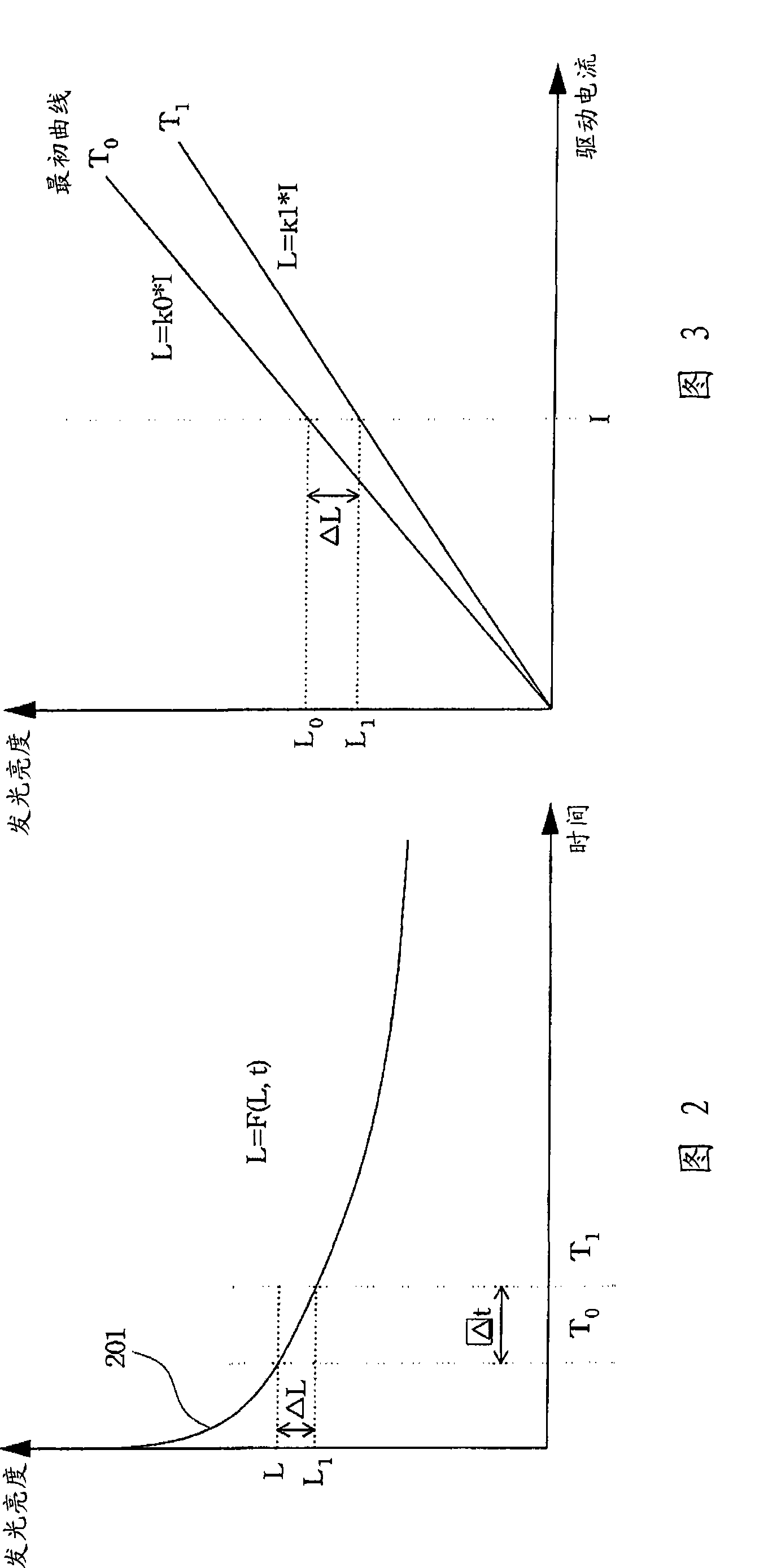
[0024] However, the luminous brightness under a constant current will decrease with the increase of the use time...


PUM


Abstract

The present invention discloses a method for driving a light emitting diode according to a required luminance, wherein an actual luminance of the light emitting diode decays with time and a correlation there between is represented by a life-time curve. The method comprises the following steps. First, the driving current is correlated with the required luminance by an initial coefficient is provided to the light emitting diode. Next, a length of a period of use of the light emitting diode is counted. Then, a slope of the life-time curve corresponding to the required luminance is stored. Finally, a new coefficient from the length of the period of use, the slope of the life-time curve and the initial coefficient is derived.

Description

technical field [0001] The present invention relates to a driving device and its operating method, more particularly to a light emitting diode driving device and its operating method. Background technique [0002] The LED array can be used to form a two-dimensional flat-panel display, and the LEDs can be formed on a transparent or semiconductor substrate to emit monochromatic light or colored light to form a monochromatic or color flat-panel display. [0003] The luminous intensity of the light emitting diodes will gradually decay with the increase of usage time, and different light emitting diodes have different decay rates, resulting in uneven display brightness of the flat panel display. Generally speaking, the light intensity of LEDs is related to the magnitude of the driving current supplied to the LEDs. Therefore, providing different magnitudes of driving currents to different LEDs can improve the inconsistency of the light intensity. A known technique is to use a pho...

Claims


Application Information

Patent Timeline
Patent Type & Authority Applications(China)
IPC IPC(8): G09G3/32G09G5/10H05B37/02
CPCG09G2360/16G09G3/32G09G2320/0233G09G2320/048
Inventor 吴炳升卜令楷邱郁文
Owner HIMAX TECH LTD
Why Eureka
Try Eureka