Method for implementing liquid crystal display drive circuit and source pole drive circuit module

A driving circuit and liquid crystal display technology, applied in static indicators, instruments, etc., can solve problems such as the difficulty of area design, and achieve the effects of low power consumption, high degree of integration, and small size

Active Publication Date: 2009-04-22
SUZHOU PIXCIR MICROELECTRONICS
View PDF0 Cites 12 Cited by
  • Summary
  • Abstract
  • Description
  • Claims
  • Application Information

AI Technical Summary

Problems solved by technology

[0004] In order to solve the problems of power consumption, area, design difficulty and stability, the present invention provides an implementation method of a liquid crystal display drive circuit and a source drive circuit module

Method used


Image

  • Method for implementing liquid crystal display drive circuit and source pole drive circuit module
  • Method for implementing liquid crystal display drive circuit and source pole drive circuit module
  • Method for implementing liquid crystal display drive circuit and source pole drive circuit module

Examples


Embodiment 1

[0028] A method for realizing a liquid crystal display drive circuit, characterized in that:

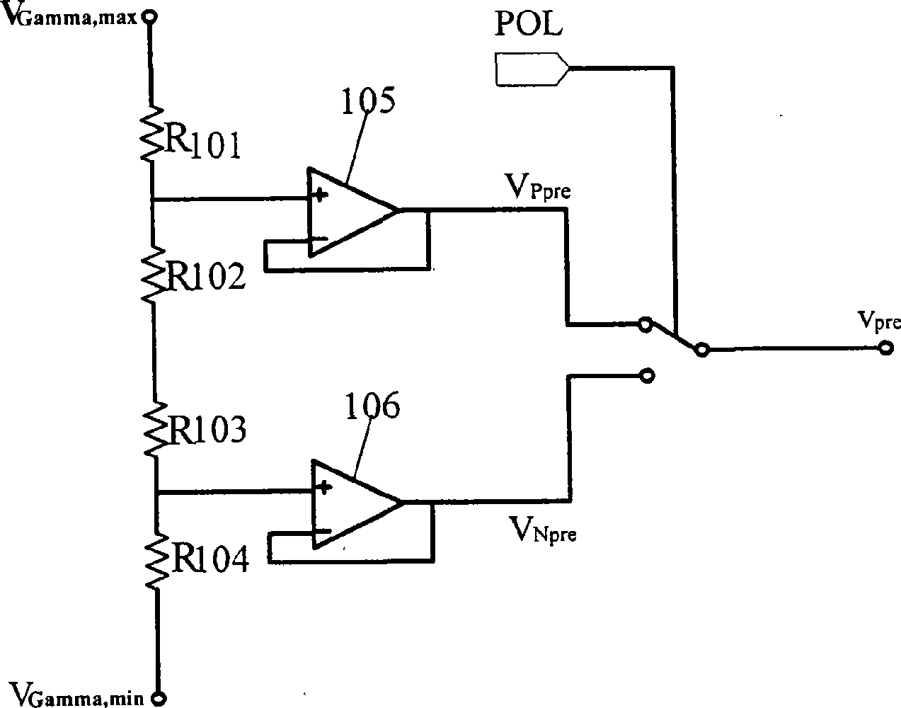
[0029]In the first step, the maximum gamma voltage (VGamma, max) and the minimum gamma voltage (VGamma, min) are respectively used as the input voltages of the precharge voltage generation circuit (100), and the positive polarity is generated by the precharge voltage generation circuit (100). The precharge voltage Vpper and the negative polarity precharge voltage Vnper, the voltage value of the positive polarity precharge voltage Vpper is the sum of 3 / 4 of the maximum gamma voltage (VGamma, max) and 1 / 4 of the minimum gamma voltage (VGamma, min), The voltage value of the negative polarity precharge voltage Vnper is the sum of 1 / 4 the maximum gamma voltage (VGamma, max) and 3 / 4 the minimum gamma voltage (VGamma, min); according to the polarity (POL) of the line to be displayed, select The positive polarity precharge voltage Vpper or the negative polarity precharge voltage Vnper is use...

Embodiment 2

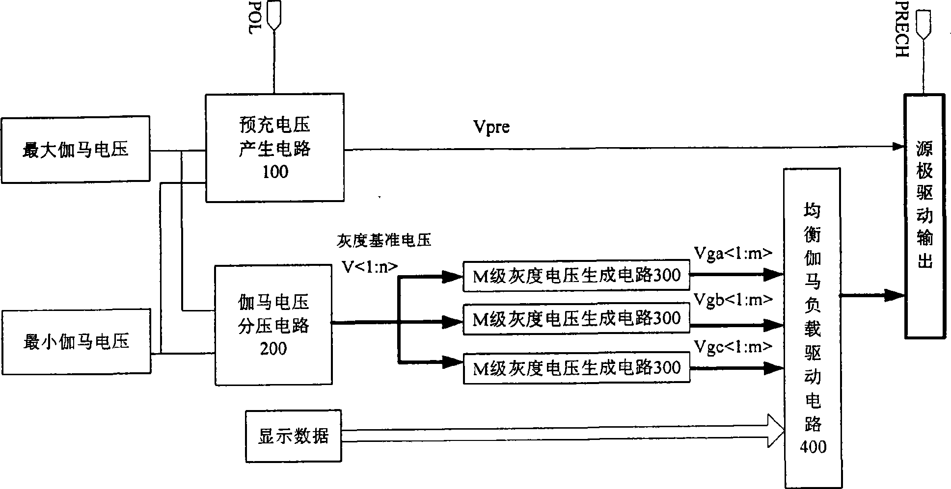
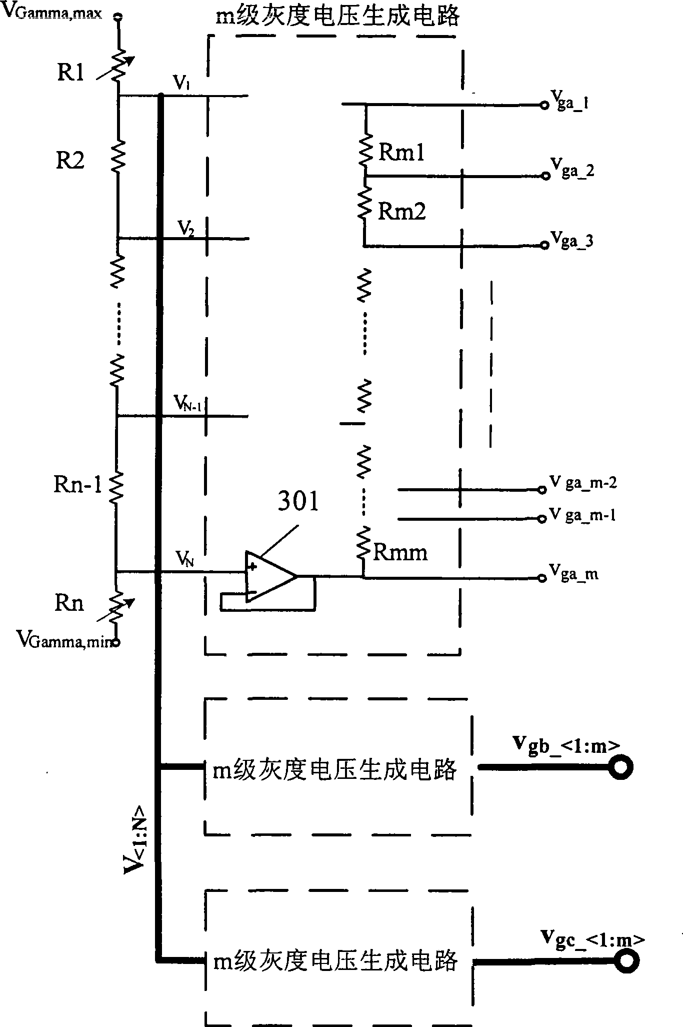
[0034] A source drive circuit module, composed of a precharge voltage generation circuit 100, a gamma voltage divider circuit 200, 2 to 4 sets of M-level grayscale voltage generation circuits 300 and a balanced gamma load drive circuit 400, the maximum gamma voltage (VGamma, max) and the minimum gamma voltage (VGamma, min) are respectively connected to the input terminals of the precharge voltage generation circuit 100 and the gamma voltage divider circuit 200, and the output of the precharge voltage generation circuit 100 is the precharge voltage Vper , the precharge voltage Vper is the positive polarity precharge voltage Vpper or the negative polarity precharge voltage Vnper; the output of the gamma voltage divider circuit 200 is N grayscale reference voltages V 1 , V 2 ,...,V N , N gray scale reference voltage V 1 , V 2 ,...,V N Three sets of M-level grayscale voltage generating circuits 300 are respectively connected, and the outputs of the M-level grayscale voltage ge...


PUM


Abstract

The invention discloses an implementation method of an LCD drive circuit and a source electrode drive circuit module. The source electrode drive circuit module is characterized by consisting of a precharge voltage generation circuit (100), a gamma voltage division circuit (200), two to four groups of M-level gray scale generation circuits (300) and an equilibrium gamma load drive circuit (400), wherein, output of the precharge voltage generation circuit (100) is a precharge voltage Vper which is a positive precharge voltage Vpper or a negative precharge voltage Vnper, the output of the gamma voltage division circuit (200) is N gray scale reference voltages, namely, V1, V2 to VN, and the N gray scale reference voltages V1, V2 to VN are respectively connected with the two to four groups of M-level gray scale generation circuits (300) the output of which is two to four groups of gray scale voltages, the gray scale voltages and display data (G_DATA) are jointly connected to an input terminal of the equilibrium gamma load drive circuit (400), and the gamma drive output voltage and the precharge voltage Vper are taken as the source electrode drive output.

Description

technical field [0001] The present invention relates to a method for realizing a liquid crystal drive module circuit and its drive circuit, in particular to a method for realizing a liquid crystal display drive circuit for a source drive chip in a small and medium-sized digital panel or a source drive part in a single-chip integrated drive chip. Source drive circuit module. Background technique [0002] In the LCD driver chip, the function of the source driver is to convert the externally input digital signal into a gray-scale voltage analog signal with current driving capability and drive it to charge the liquid crystal dot matrix on the LCD panel, so that the voltage at both ends of the liquid crystal display capacitor To achieve the corresponding gray voltage value, to achieve the purpose of displaying color images. Its display quality is closely related to the drive capability of the drive circuit and the accuracy of the grayscale voltage. Now, with the increasing powe...

Claims


Application Information

Patent Timeline
Patent Type & Authority Applications(China)
IPC IPC(8): G09G3/36
Inventor 丁行波洪锦维
Owner SUZHOU PIXCIR MICROELECTRONICS
Why Eureka
Try Eureka