Glass antenna for an automobile

A technology for glass antennas and car window glass, applied to antennas, windshields, resonant antennas, etc., can solve the problems of wide heating wires, loss of vision, and reduce the resistance value of heating wires 44, and achieve the effect of improving antenna gain

Active Publication Date: 2009-04-22
ASAHI GLASS CO LTD
View PDF1 Cites 14 Cited by
  • Summary
  • Abstract
  • Description
  • Claims
  • Application Information

AI Technical Summary

Problems solved by technology

[0003] However, in this prior art example, the wire length of the highest heating wire 44 having a zigzag shape is too long, so it is necessary to reduce the resistance value of the highest heating wire 44 per unit length.
The line width of the heating wire 44 of the highest position is too large in this way, and there is a problem of detrimental vision

Method used


Image

  • Glass antenna for an automobile
  • Glass antenna for an automobile
  • Glass antenna for an automobile

Examples


Embodiment Construction

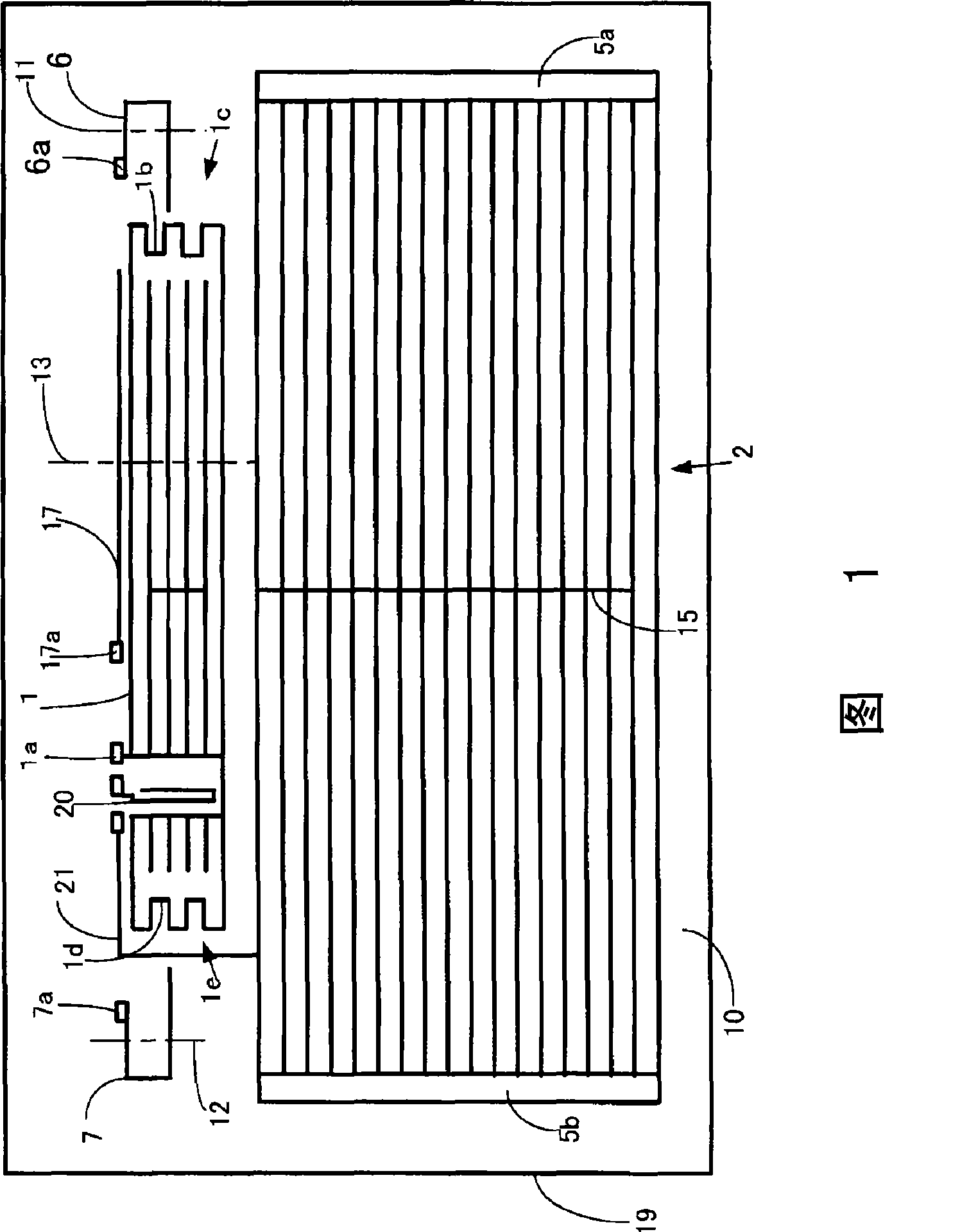
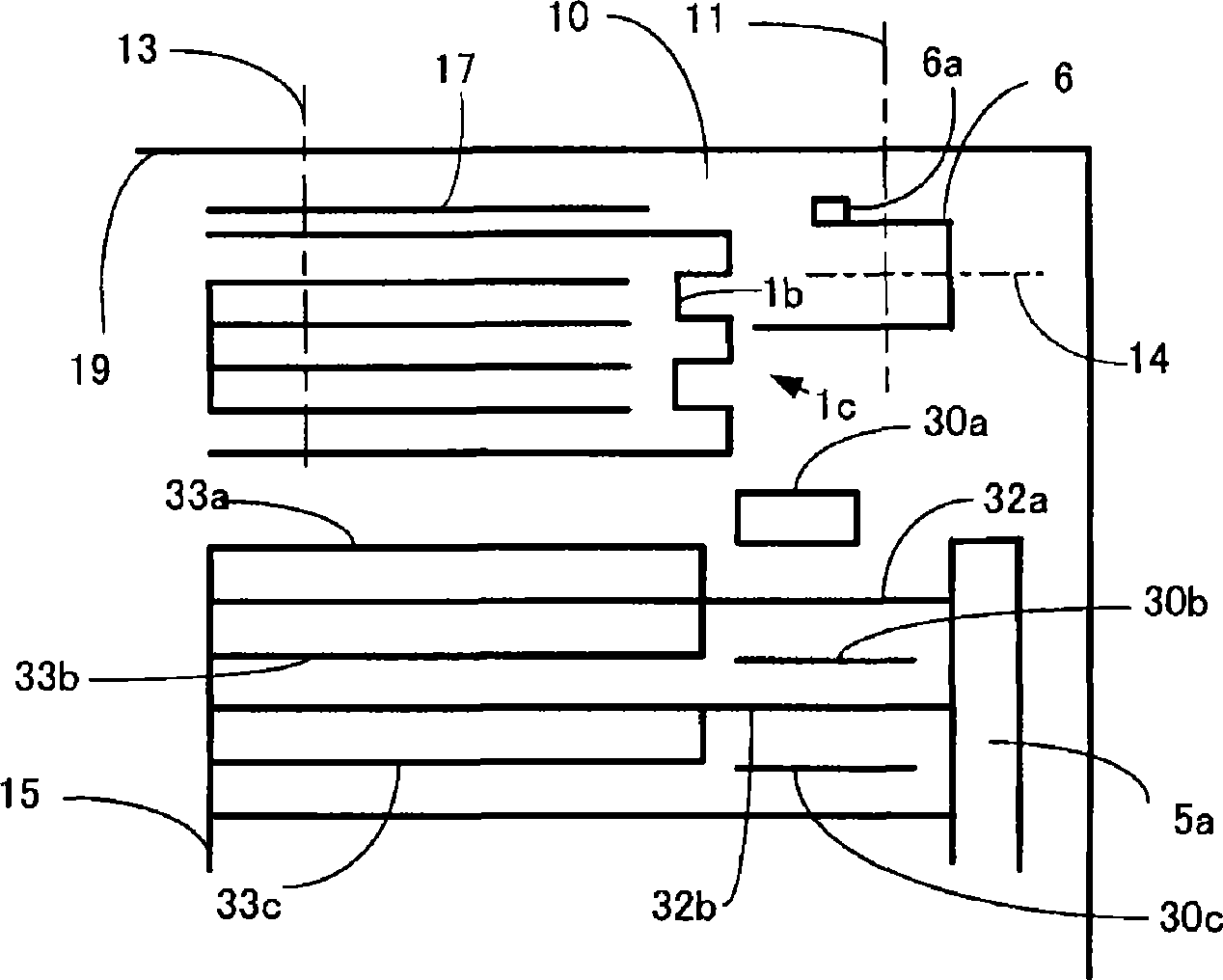
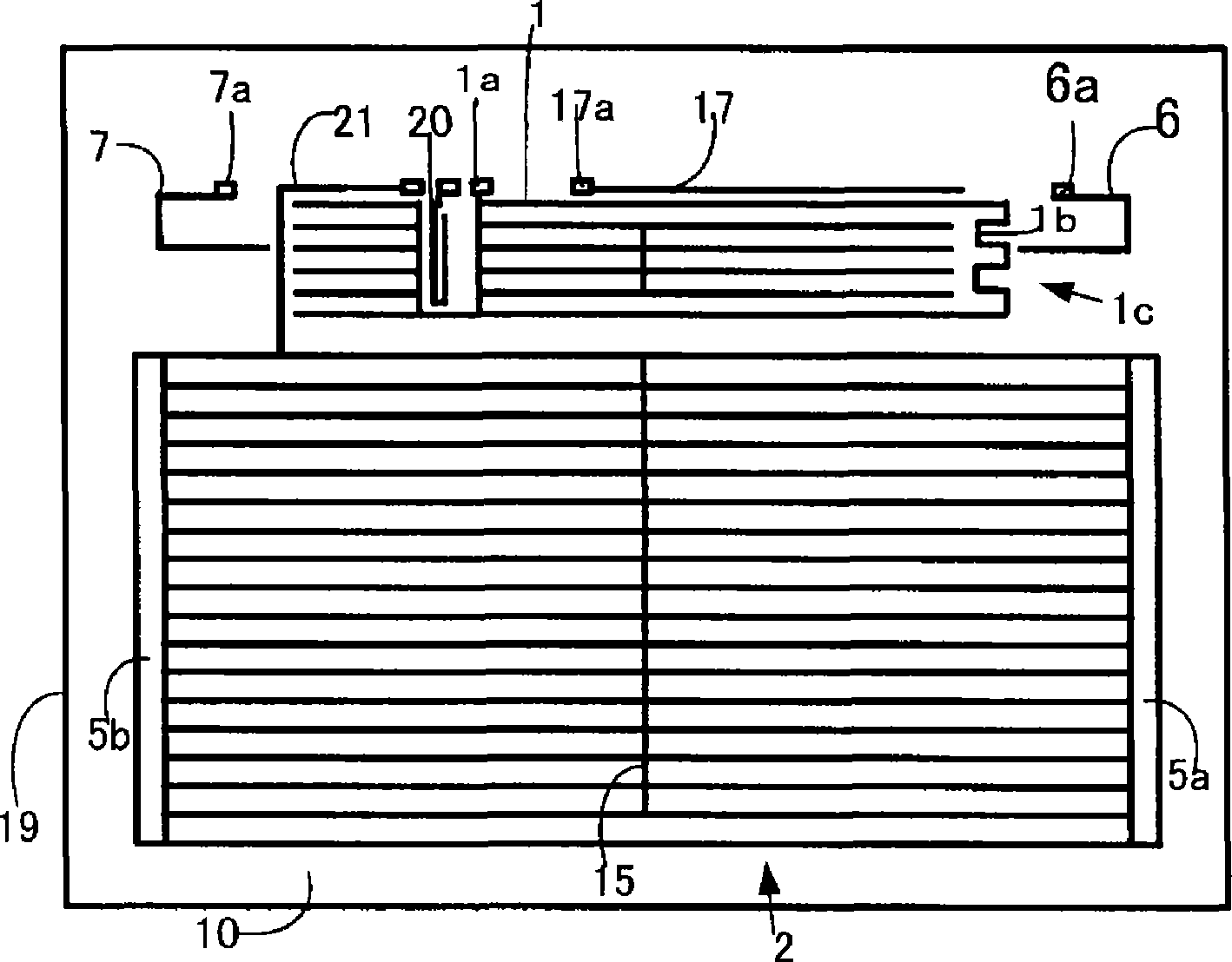
[0042] Hereinafter, the glass antenna for automobiles of the present invention will be described in detail based on the preferred embodiments shown in the accompanying drawings. FIG. 1 is a plan view showing an embodiment of the automotive glass antenna of the present invention. In addition, although FIG. 1 is the case of seeing from the inside of a vehicle, it may be the case of seeing from the outside of a vehicle.

[0043] In FIG. 1 , 1 is an antenna conductor for L-band, 1a is a feeding portion of the antenna conductor for L-band, 1b and 1d are detours, 1c is a first predetermined direction extension portion, and 1e is a second predetermined direction extension part, 2 is a heating wire, 5a is a first bus bar, 5b is a second bus bar, 6 is a first H-band antenna conductor, 6a is a feeder for the first H-band antenna conductor 6, and 7 is a second The antenna conductor for H-band, 7a is the feeder of the second antenna conductor 7 for H-band, 10 is the rear window glass, 11...


PUM


Abstract

A glass antenna for an automobile improving antenna gain is provided. The glass antenna can receive two wavelength bands, that are a first wavelength band and a second wavelength band higher than the first wavelength band, and provided that the first wavelength band is designated as H band and the second wavelength band is designated as L band, antenna conductors 6, 7 for H band each having a shape and dimension configured to receive H band is provided on a rear glass plate 10 for an automobile, and an antenna conductor 1 for L band having a shape and dimension configured to receive L band isprovided on the rear window glass plate 10, the antenna conductors 6, 7 for H band and the antenna conductor 1 for L band constitute two types of antenna conductors, the antenna conductor 1 for L band has a portion extending in a predetermined direction, and provided that the portion is designated as a predetermined direction extending portion 1c, the predetermined direction extending portion 1c has a detour portion 1b.

Description

technical field [0001] The present invention relates to a glass antenna for automobiles suitable for receiving domestic terrestrial digital TV broadcasting (470-770 MHz), analog TV broadcasting in UHF band (473-767 MHz) or digital TV broadcasting in the United States (698-806 MHz). Background technique [0002] as always Image 6 The shown glass antenna for automobiles for receiving the digital television broadcasting band (for example, refer to Patent Document 1). In this prior art example, a defogger composed of a plurality of heating wires 43 and bus bars 45 is provided on the rear window glass 10 , and an antenna conductor 41 and a feeding point 42 are provided. The uppermost heating wire 44 directly below the antenna conductor 41 has a meandering shape. With this configuration, in the digital television broadcasting band, the influence of the heating wires 43 and 44 on the antenna conductor 41 can be reduced, and the antenna gain in the digital television broadcasting ...

Claims


Application Information

Patent Timeline
Patent Type & Authority Applications(China)
IPC IPC(8): H01Q1/32H01Q1/38H01Q5/00H01Q9/04B60J1/18H01Q9/42H01Q21/28
CPCH01Q1/1271H01Q1/1278H01Q5/00H01Q5/0072H01Q5/40H01Q1/32H01Q1/27
Inventor 下宪一郎渡边充朗伊东昌辉
Owner ASAHI GLASS CO LTD
Why Eureka
Try Eureka