
Droplet deposition apparatus

A deposition device and droplet technology, applied to the components of the droplet deposition device and the cover of the droplet deposition device, can solve the problems of performance degradation, pressure loss, etc., reduce the possibility, improve the service life, and simplify the manufacturing process Effect

Active Publication Date: 2013-10-30
XAAR TECH LTD
View PDF6 Cites 0 Cited by
  • Summary
  • Abstract
  • Description
  • Claims
  • Application Information

AI Technical Summary

Problems solved by technology

In this arrangement, the displacement is typically around 50 nm, and it is understood that a corresponding change in channel dimension due to channel compliance will result in a rapid loss of pressurization with a corresponding drop in performance

Method used


Image

  • Droplet deposition apparatus
  • Droplet deposition apparatus
  • Droplet deposition apparatus

Examples


Embodiment Construction

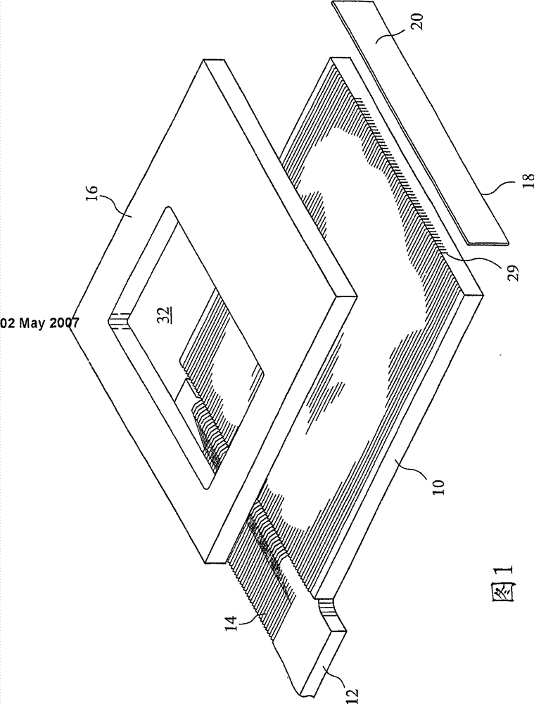
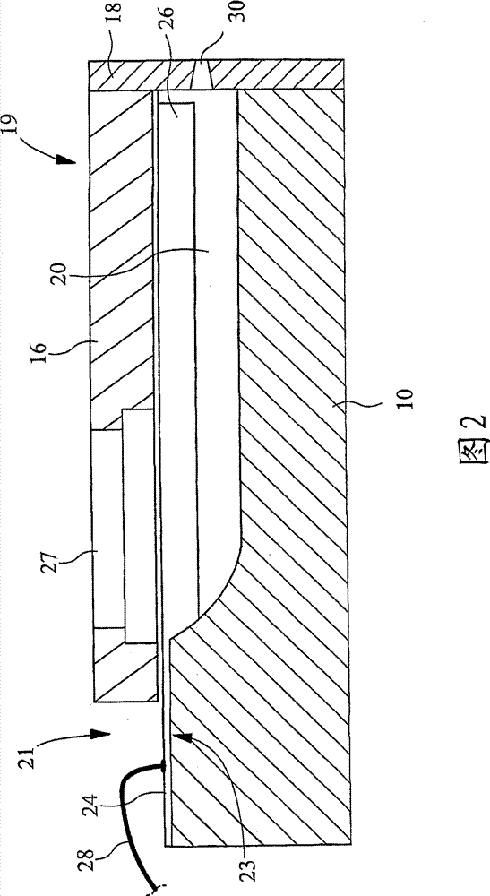
[0038] figure 1 An exploded perspective view shows an inkjet print head incorporating a piezoelectric wall actuator operating in shear mode. The inkjet print head includes a substrate 10 made of piezoelectric material mounted on a circuit board 12, and only the portion of the circuit board 12 that shows the connecting printed lines 14 is shown. A plurality of elongated channels 29 are formed in the base. The cover 16 bonded to the substrate 10 during assembly is shown above its assembled position. A nozzle plate 18 is also shown near the base of the print head, and a plurality of nozzles (not shown) are formed in the nozzle plate. The nozzle plate 18 is generally a polymer sheet coated with a low energy surface coating 20 on the outer surface.

[0039] figure 1 The illustrated cover 16 is formed of a material thermally matched to the base member 10. One solution is to use piezoelectric ceramics similar to those used for the substrate, so that when the cover is bonded to the su...


PUM


Abstract

Droplet deposition apparatus comprising: an array of fluid chambers, each fluid chamber defined by a pair of opposing chamber walls comprising piezoelectric material separated one from the other by a chamber wall separation, and in fluid communication with a nozzle for droplet ejection therefrom; and a cover member joined to the edges of said chamber walls, thereby sealing one side of said chambers; wherein the thickness of the cover member is less than 150 µm.

Description

Technical field [0001] The present invention relates to a component for a droplet deposition device, and more particularly to a cover for a droplet deposition device. The invention is particularly suitable for the field of on-demand inkjet printing. Background technique [0002] One known inkjet print head configuration uses piezoelectric actuation elements to generate and manipulate pressure waves in a fluid ejection chamber. In order to operate reliably and maintain a sufficient droplet ejection velocity, a minimum pressure must be generated in the chamber, usually about 1 bar. It should be understood that in order to generate such pressure, the chamber must exhibit proper stiffness (or lack of compliance). Therefore, the compliance of the fluid chamber is an important criterion for chamber design, and a large number of technical solutions have been proposed to keep the compliance of the fluid ejection chamber to a minimum. [0003] For example, EP 0712355 describes a bonding ...

Claims


Application Information

Patent Timeline
Patent Type & Authority Patents(China)
IPC IPC(8): B41J2/14
CPCB41J2002/14362B41J2002/14419B41J2/14209B41J2/01B41J2/14
Inventor 保罗·雷蒙德·特鲁里斯蒂芬·坦普尔
Owner XAAR TECH LTD
Learn More