
Plastic molding machining process

A technology of blister molding and processing technology, applied in the field of blister molding, can solve the problems of increasing the roundness and other issues, and achieve the effect of reducing the possibility of bubbles and reducing the rate of defective products.

Inactive Publication Date: 2020-02-28
SUZHOU BOLICEN PRECISION MACHINERY CO LTD
View PDF4 Cites 0 Cited by
  • Summary
  • Abstract
  • Description
  • Claims
  • Application Information

AI Technical Summary

Problems solved by technology

[0003] Blister products adopt the technology of thick plate blister and thin plate blister, and the finished product may have defects such as pull lines, scratches, crystal points, bubbles, water ripples, etc. Some defects can be avoided during processing, for example, the defects of pull wires can be Re-modify the mold (reduce the height and increase the smoothness of the garden) and add an additional pressure mold (called the upper mold) to solve the problem of water ripples can be solved by adjusting the heating temperature so that the heating temperature of the plastic product is just enough to ensure its absorption. Plastic molding, there will be no vacuum adsorption and additional tension molding, so as to avoid water ripples caused by incomplete heating to a suitable temperature for processing and molding, and scratches can improve the fine production of each structure, so that each straight edge chamfers round to avoid scratches, but some defects cannot be avoided through the improvement of the blister-related structure itself, such as crystal points and bubbles. Many crystal points are caused by dust invisible to the naked eye, and bubbles are plastic products that heat raw materials. Air is contained in it, even if it is heated and formed, the air is still in the plastic product, so that air bubbles appear in the finished product; therefore, the market urgently needs to develop a blister forming process to help people solve the existing problems

Method used


Image

  • Plastic molding machining process

Examples


Embodiment Construction

[0028] The following will clearly and completely describe the technical solutions in the embodiments of the present invention with reference to the accompanying drawings in the embodiments of the present invention. Obviously, the described embodiments are only some, not all, embodiments of the present invention.

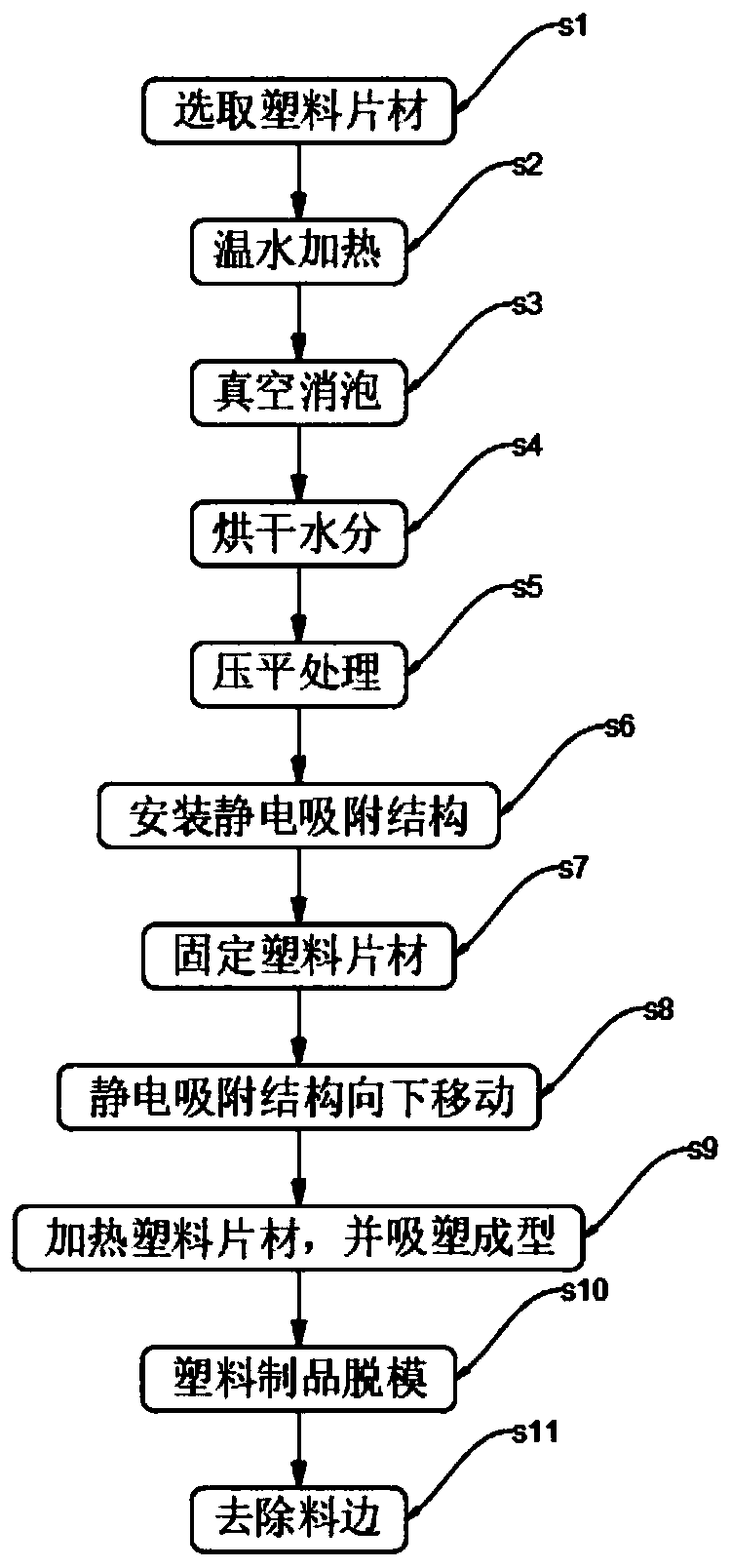
[0029] see figure 1 , an embodiment provided by the present invention: a blister forming process, comprising the following steps:

[0030] S1: Select plastic sheet;

[0031] The selected size of the plastic sheet is smaller than the size of the traditional plastic sheet used to manufacture the plastic product, and the selected thickness of the plastic sheet is greater than the thickness of the traditional plastic sheet used to manufacture the plastic product;

[0032] Because there is defoaming in the subsequent steps and flattening to eliminate holes, the plastic sheet taken at the beginning is smaller and thicker than the plastic sheet required for the plastic pro...


PUM


Abstract

The invention discloses a plastic molding machining process, and relates to the plastic molding related field. Through the related improvement of the machining process, the reject ratio of final plastic molding products is reduced, and the influences of various defects on the appearance and properties of the finished products are avoided. The process includes the following steps of S1, selecting aplastic sheet; S2, putting the plastic sheet in warm water to be heated; S3, putting the heated plastic sheet in a vacuum box for vacuum defoaming; S4, drying the defoamed plastic sheet to remove surface water; S5, flattening the plastic sheet defoamed in the step S3 through a flattening device; S6, arranging an electrostatic adsorption structure at the upper end of a plastic suction mold of a plastic vacuum forming machine; S7, putting the plastic sheet obtained in the step S5 on the upper end of the plastic suction mold of the plastic vacuum forming machine to be fixed; S8, moving down theelectrostatic adsorption structure in the step S6; S9, heating the plastic sheet and performing plastic molding; S10, making a formed plastic product disengaged from the plastic suction mold; and S11,removing edges of the finished plastic product.

Description

technical field [0001] The invention relates to the related field of plastic forming, in particular to a processing technology of plastic forming. Background technique [0002] Blister molding is a kind of plastic processing technology. The main principle is to heat and soften the flat plastic hard sheet, then vacuum absorb it on the surface of the mold, and shape it after cooling. It is a technical process applied to various industries. Blister products are widely used, mainly used in electronics, electrical appliances industry, food industry, hardware tools, cosmetics industry, toy industry, daily necessities industry, medicine, health care products, automobiles, stationery, stationery, stationery and other industries. [0003] Blister products adopt the technology of thick plate blister and thin plate blister, and the finished product may have defects such as pull lines, scratches, crystal points, bubbles, water ripples, etc. Some defects can be avoided during processing,...

Claims


Application Information

Patent Timeline
Patent Type & Authority Applications(China)
IPC IPC(8): B29C51/10B29C51/26B29C33/72
CPCB29C33/72B29C51/10B29C51/264
Inventor 罗成
Owner SUZHOU BOLICEN PRECISION MACHINERY CO LTD
Learn More