New drive mode of straight channel type vibration machine and drive structure thereof

A technology of transmission structure and vibrating machine, which is applied in the direction of vibrating fluid and grain processing, etc. It can solve the problems of torsional vibration of the tank body, easy damage of the vibration motor, large torque of the tank body, etc., and achieve the requirement of reducing rigidity and reducing the implementation cost , The effect of stable vibration conditions

Active Publication Date: 2011-09-21
HUZHOU XING XING ABRASIVE
View PDF0 Cites 0 Cited by
  • Summary
  • Abstract
  • Description
  • Claims
  • Application Information

AI Technical Summary

Problems solved by technology

Because the vibration motor is in a vibrating state during the working process, the vibration motor is extremely easy to damage, and the vibration motor is expensive, which is 3 to 4 times that of ordinary motors.
For the straight trough vibrating machine with a long tank, because the tank is too long, it is difficult for a single vibration motor to drive evenly in the vibration plane, and two vibration motors need to be installed. After using two vibration motors, not only the cost It is greatly improved, and because the two vibration motors cannot be completely synchronized when they are working, the tank is subjected to a large torque, and the tank is distorted and vibrated, which cannot achieve the expected effect, and the rigidity of the tank is required very high. , which increases the cost to a certain extent
The incomplete synchronous vibration of the other two vibrating motors will lead to the inconsistency of the positions of the eccentric wheels, making the working condition of the vibrating machine unstable, causing the trajectory of the abrasive to be disordered, and the expected grinding effect cannot be achieved.
Therefore, the transmission mode of the existing straight trough vibrator still needs to be improved

Method used


Image

  • New drive mode of straight channel type vibration machine and drive structure thereof
  • New drive mode of straight channel type vibration machine and drive structure thereof
  • New drive mode of straight channel type vibration machine and drive structure thereof

Examples


Embodiment Construction

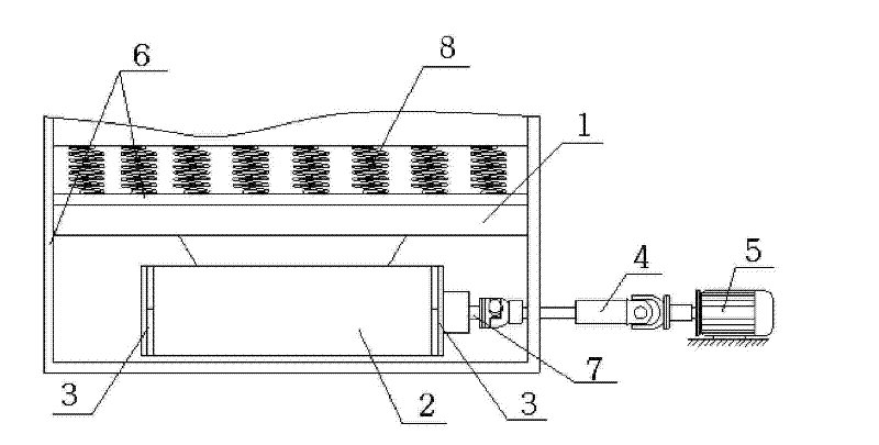
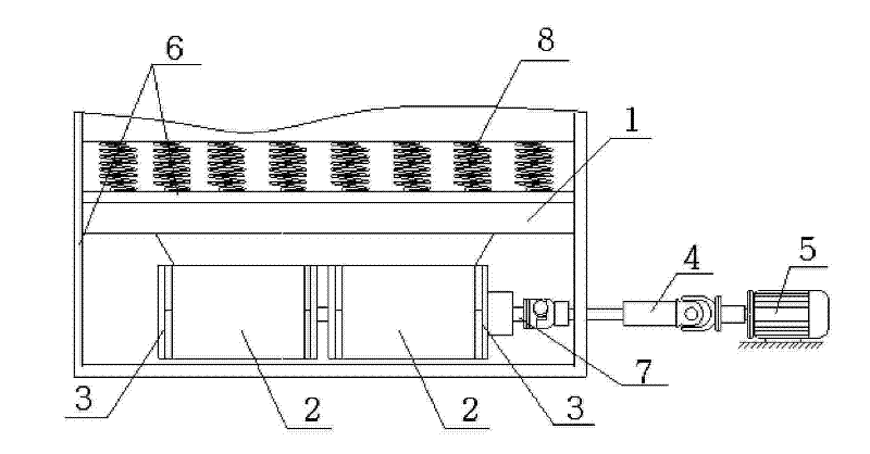
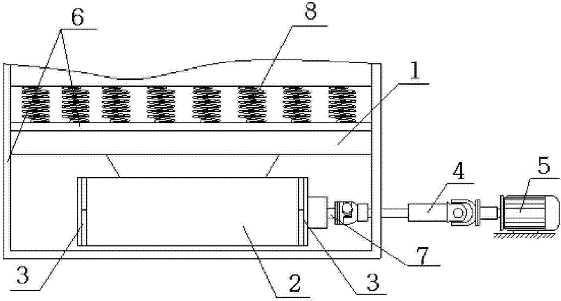
[0011] The embodiment of the present invention: a novel transmission method of a straight slot type vibrating machine, which drives the universal coupling through a motor, and the universal coupling drives the eccentric wheel shaft and the eccentric block group in the bearing seat at the bottom of the tank. Make the vibrator tank vibrate regularly.

[0012] The transmission structure made according to the new transmission method of the straight groove type vibrating machine: figure 1 As shown, the entire vibrating machine is placed on the working ground through the vibrating machine base 6, and the bearing seat 2 is connected under the trough body 1 of the straight groove vibrating machine; the bearing seat 2 is installed with an eccentric wheel shaft 7, and each end is installed with a set The eccentric wheel 3; the eccentric wheel shaft 7 is connected with the universal coupling 4; the other end of the universal coupling 4 is connected with the output shaft of the motor 5. The ...


PUM


Abstract

The invention discloses a novel transmission mode of a straight groove vibration machine and a transmission structure thereof. In the method, a universal coupler is driven by a motor, and an eccentric wheel shaft and an eccentric block group in a bearing seat at the bottom of a groove body are driven by the universal coupler so as to lead the groove body to vibrate regularly. The structure comprises the groove body (1), the lower part of which is connected with the bearing seat (2); the bearing seat (2) is internally provided with the eccentric wheel shaft (7), and two ends of the eccentric wheel shaft (7) are respectively provided with a group of eccentric wheels (3); the eccentric wheel shaft (7) is connected with the universal coupler (4); and the other end of the universal coupler (4)is connected with an output shaft of the motor (5). The invention effectively eliminates the twist of the groove body caused by asynchronous vibration sources, and the common motor replaces the expensive vibration motor, thus reducing the requirement on the groove body stiffness, improving the stability of the vibration machine, and leading the grinding vibration to be stable. The invention has good grinding effect, saves the cost, and is convenient for maintenance.

Description

Technical field [0001] The invention relates to a transmission mode and a transmission structure for a straight slot type vibration machine, belonging to the technical field of vibration transmission. technical background [0002] In the field of abrasive grinding technology, straight trough vibrating machines generally adopt a vibration motor installed below the trough body, and the vibration motor is used to drive the trough body to vibrate to achieve grinding of the workpiece. Because the vibration motor is in a state of vibration during the working process, the vibration motor is extremely easy to be damaged, and the price of the vibration motor is expensive, which is 3 to 4 times that of the ordinary motor. For the straight-slot type vibrator with a longer tank, because the tank is too long, it is difficult for a single vibration motor to drive uniformly in the vibration plane. It is necessary to install two vibration motors. After using two vibration motors, it is not only ...

Claims


Application Information

Patent Timeline
Patent Type & Authority Patents(China)
IPC IPC(8): B06B1/16B02C19/16B02C17/14
Inventor 徐金发
Owner HUZHOU XING XING ABRASIVE
Why Eureka
Try Eureka