Grinding-bed static head rack capable of realizing accurate ultra micro-finishing
A static pressure head and ultra-precision technology, which is applied to the parts of grinding machine tools, ultra-finishing machines, grinding/polishing equipment, etc., can solve the problems affecting the improvement of the surface quality of the grinding wheel grinding workpiece, and the surface contour of the grinding wheel grinding workpiece. Reduced precision, easy changes in bearing clearances, etc., to achieve the effect of reducing equipment materials, saving equipment production costs, and reducing equipment maintenance costs
- Summary
- Abstract
- Description
- Claims
- Application Information
AI Technical Summary
Problems solved by technology
Method used
Image
Examples
Embodiment 1
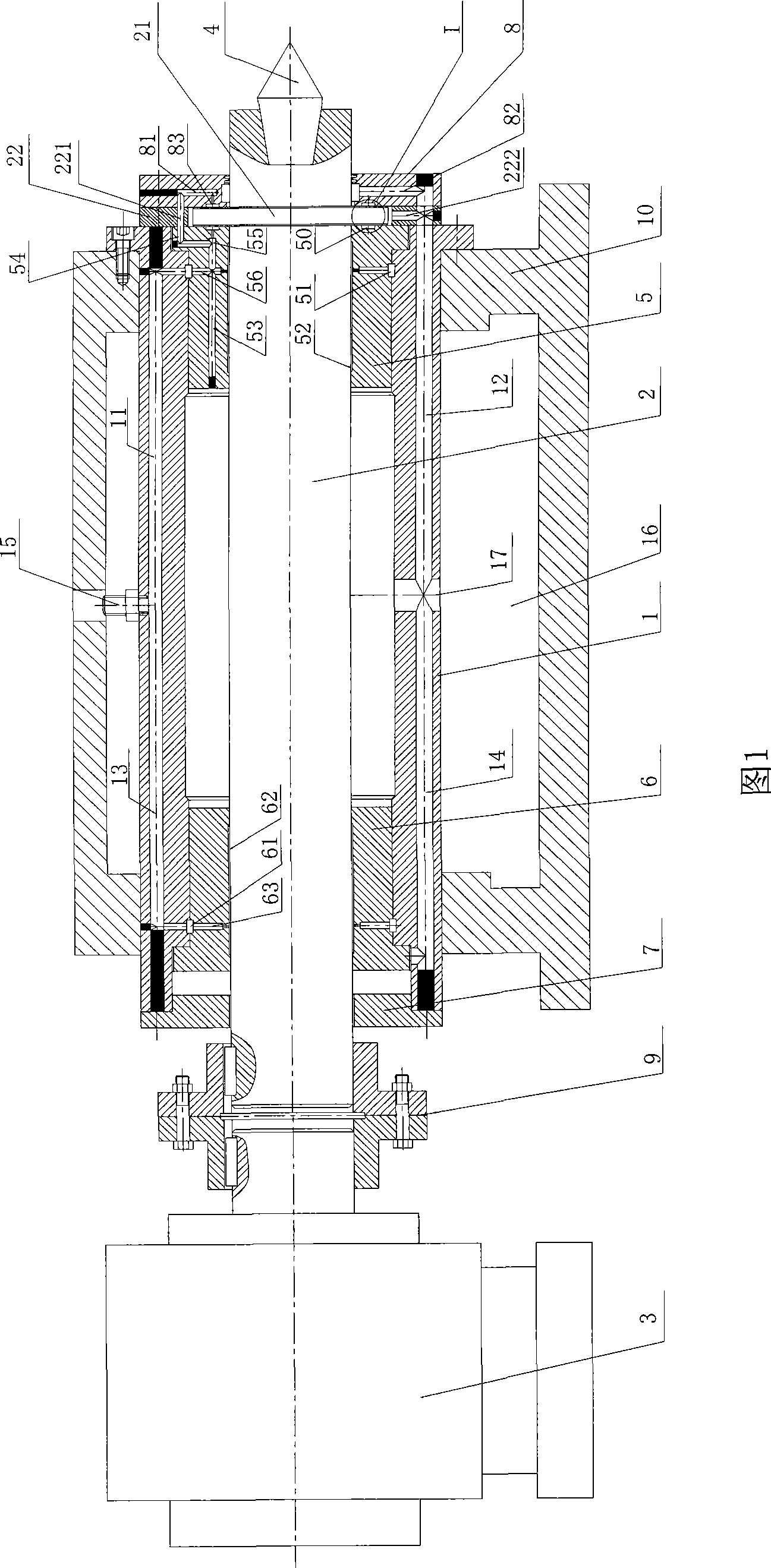
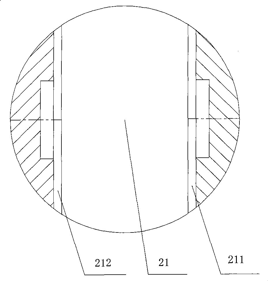
[0035] Embodiment 1: as figure 1 , image 3 As shown, the hydrostatic headstock of a grinding machine for ultra-precision grinding of the present invention includes a sleeve 1, a headstock spindle 2, a support box 10, a headstock motor 3 and a headstock tip 4, and the headstock tip 4 is installed on The front end of the headstock main shaft 2 and the headstock motor 3 are directly connected to the rear end of the headstock main shaft 2 through a coupling 9, so as to reduce the space occupied by the equipment and reduce the cost of the equipment. The rear end of the sleeve 1 is equipped with a rear end cover 7, the front end of the sleeve 1 is equipped with a front end cover 8, and the sleeve 1 is provided with a forward liquid channel 11, a front liquid return channel 12, a rear liquid feed channel 13, and a rear liquid return channel. The channel 14, the liquid supply channel 15 and the sleeve liquid return hole 17 located in the middle of the sleeve 1, the support box 10 is...
Embodiment 2
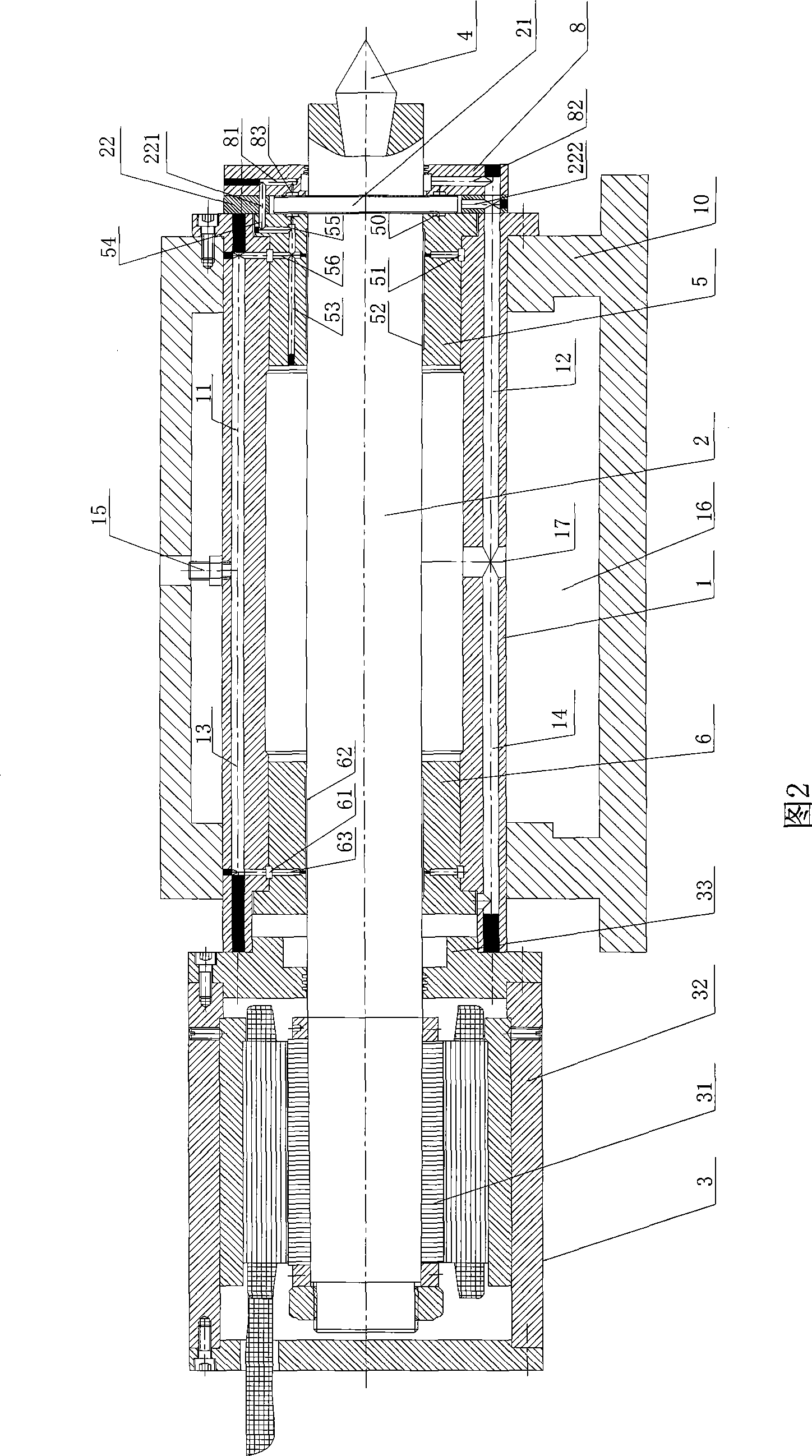
[0044] Embodiment 2: as figure 2 As shown, the hydrostatic headstock of a grinding machine for ultra-precision grinding of the present invention includes a sleeve 1, a headstock spindle 2, a support box 10, a headstock motor 3 and a headstock tip 4, and the headstock tip 4 is installed on The front end of the headstock main shaft 2, the rear end of the headstock main shaft 2 is set in the rotor 31 of the headstock motor 3, the end of the headstock motor 3 close to the sleeve 1 is provided with a flange 33, and the stator shell 32 of the headstock motor 3 passes through the flange 33 is fixed on the sleeve 1, and the function of the motor and the function of the headstock spindle 2 are structurally integrated, eliminating the need for complicated intermediate transmission links, and has the advantages of compact structure, light weight, small inertia, small vibration and low noise , fast response and other advantages. The front end of the sleeve 1 is equipped with a front end...
PUM
 Abstract
Description
Claims
Application Information
 - R&D
- Intellectual Property
- Life Sciences
- Materials
- Tech Scout
- Unparalleled Data Quality
- Higher Quality Content
- 60% Fewer Hallucinations
Browse by: Latest US Patents, China's latest patents, Technical Efficacy Thesaurus, Application Domain, Technology Topic, Popular Technical Reports.
© 2025 PatSnap. All rights reserved.Legal|Privacy policy|Modern Slavery Act Transparency Statement|Sitemap|About US| Contact US: help@patsnap.com


