Electronic lock core with clutch device and electronic lock system therewith

A technology of an electronic lock system and a clutch device, applied in the field of electronic lock systems, can solve the problems of high maintenance cost, single key function and inability to apply, and achieve the effects of reducing maintenance cost, good anti-pick performance and high integration.

Active Publication Date: 2009-04-29
FOSHAN POWER SUPPLY BUREAU GUANGDONG POWER GRID +2
View PDF0 Cites 31 Cited by
  • Summary
  • Abstract
  • Description
  • Claims
  • Application Information

AI Technical Summary

Problems solved by technology

[0002] At present, electronic locks on the market are mainly divided into two categories. One is the electric lock with its own power supply. This kind of lock has two major disadvantages: 1. Since the lock has a battery, the battery needs to be replaced regularly, so the maintenance cost is very high. high
2. Because the battery is placed in the lock body, the lock is large in size, so it cannot be applied to products such as padlocks, box locks, etc.
Another type of electronic lock has no power supply in the lock body, and the key provides the power required to open the lock. This type of lock is smaller in size than the above-mentioned electronic lock, but the method of timing power supply is often used for the electronic lock cylinder drive device, for example The method of continuous power supply for 5 to 10 seconds and then power failure, this method often wastes a lot of power, is not scientific enough, greatly reduces the number of times the key is unlocked, and the key has a single function, often only supplying power to the lock cylinder and storing data. no other stretch features

Method used


Image

  • Electronic lock core with clutch device and electronic lock system therewith
  • Electronic lock core with clutch device and electronic lock system therewith
  • Electronic lock core with clutch device and electronic lock system therewith

Examples


Embodiment Construction

[0067] The present invention will be described in further detail below in conjunction with the accompanying drawings and specific embodiments, but not as a limitation of the present invention.

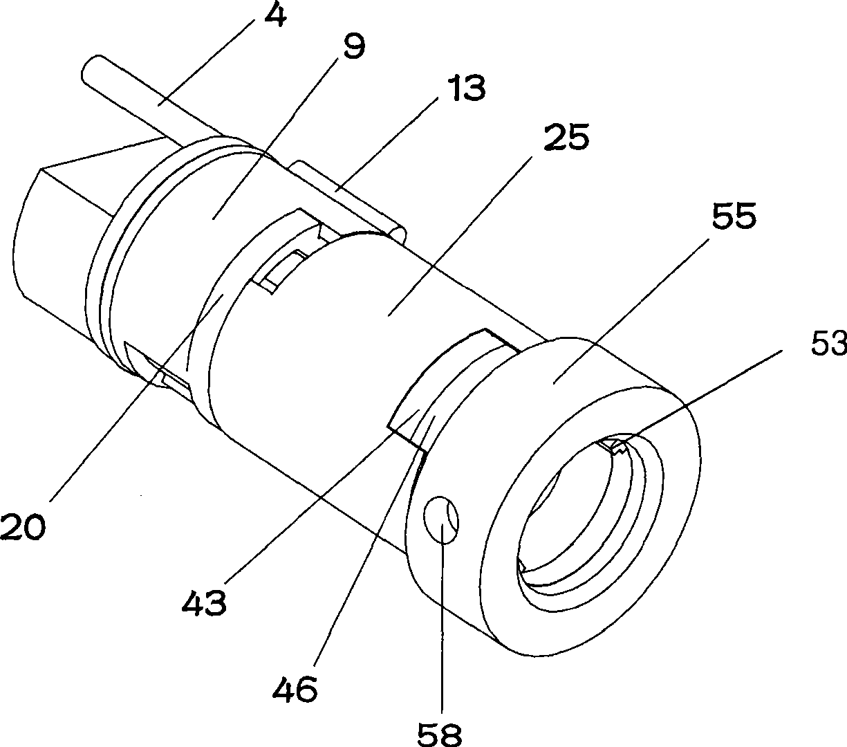
[0068] like figure 1 Shown is a schematic diagram of the overall structure of the combination of the components of the electronic lock cylinder of the present invention. The electronic lock cylinder is installed in the electronic lock cylinder installation hole 2 (combined with FIG. 6 ), and the mounting plate 55 is fixed on the On the lock housing 1, in the process of opening and closing the lock, the mounting disc 55 and the rotating clutch plate 51 do not rotate together with the electronic lock cylinder.

[0069] As shown in Figures 4 and 5, the electronic lock core includes a mechanical rotating core 9, a rotor 15, a clutch plate 20, an electronic rotating core 25, an electronic circuit device 34, an insulating sheet 41, a rotating disk 46, a rotating clutch plate 51 and The oute...


PUM


Abstract

The invention discloses an electronic lock core with clutch, which comprises a mechanical rotary core, a rotor, a clutch-plate, an electronic rotary core, a rotating disk, and a mounting disk. The rotor is arranged in the mechanical rotary core, the upper part of the rotor is provided with the clutch-plate, and the upper part of the clutch-plate is provided with the electronic rotary core; the central parts of the rotor, the clutch-plate, and the electronic rotary core are provided with through holes; the inside of the electronic rotary core is provided with an electromagnet and an electronic circuit arrangement, a contact fixing plate is arranged on the rotating disk, and a rotating clutch-plate is arranged in the mounting disk. The invention also discloses an electronic lock system including the electronic lock core, which comprises the electronic lock core, an electronic key, and a lock casing, wherein the electronic key comprises a key rod and a key casing; the key rod is provided with a rotating guide groove, the inner cavity of the key rod is provided with electronic elastic contacts, and the inside of the key casing is provided with an integrated circuit. The invention is simple in structure, and excellent in pick-proof performance. The key provides the power for the opening of electronic lock core, and the power consumption required by the electronic lock is reduced.

Description

technical field [0001] The invention relates to an electronic lock core and an electronic lock system containing the electronic lock core, in particular to an electronic lock core with a clutch device and an electronic lock system. Background technique [0002] At present, electronic locks on the market are mainly divided into two categories. One is the electric lock with its own power supply. This kind of lock has two major disadvantages: 1. Since the lock has a battery, the battery needs to be replaced regularly, so the maintenance cost is very high. high. Two, because the battery is placed in the lock body, the volume of the lock is relatively large, so it cannot be applied to products such as padlocks and box locks. Another type of electronic lock has no power supply in the lock body, and the key provides the power required to open the lock. This type of lock is smaller in size than the above-mentioned electronic lock, but the method of timing power supply is often used...

Claims


Application Information

Patent Timeline
Patent Type & Authority Applications(China)
IPC IPC(8): E05B49/00E05B19/00E05B39/04
Inventor 陈炳辉
Owner FOSHAN POWER SUPPLY BUREAU GUANGDONG POWER GRID
Why Eureka
Try Eureka