
High-temperature slag economizer
An economizer and slag technology, applied in the direction of heat exchanger types, indirect heat exchangers, fixed tubular conduit assemblies, etc., can solve problems such as blockage of heat exchange tubes
- Summary
- Abstract
- Description
- Claims
- Application Information
AI Technical Summary
Problems solved by technology
Method used
Image

Examples
Embodiment Construction
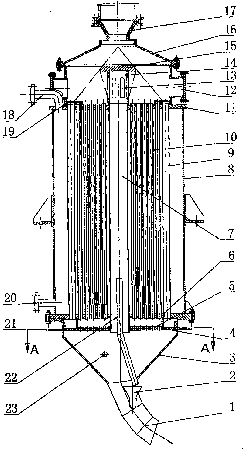
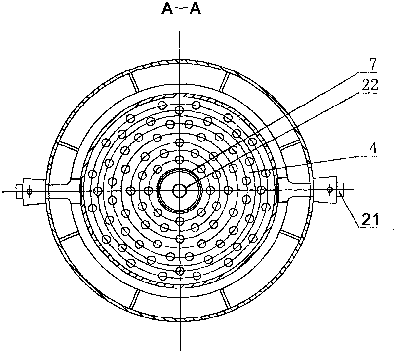
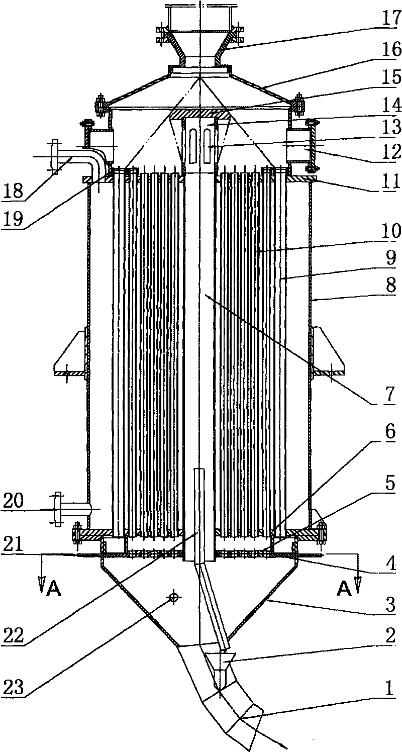
[0012] As shown in the figure, it is a high-temperature slag economizer, which mainly includes an upright casing, and the casing consists of an upper casing 16 at the top, a lower casing 3 at the bottom, and a heat exchange section between the upper and lower casings 3 body 8, the top of the upper shell 16 is provided with a slag inlet 17, the bottom of the lower shell 3 is provided with a slag outlet 1, the upper tube plate 11 is horizontally provided between the upper shell 16 and the heat exchange section cylinder 8, and the lower A lower tube plate 6 is horizontally arranged between the casing 3 and the heat exchange section cylinder body 8, and a number of heat exchange tubes 10 with openings at both ends are vertically provided between the upper tube plate 11 and the lower tube plate 6, and the heat exchange tubes 10 and the upper The tube plate 11 and the lower tube plate 6 are sealed and connected, so that the cavity outside the heat exchange tube 10 in the heat exchang...
PUM
 Abstract
Description
Claims
Application Information