
Annular wall heat reverse injection pulverized coal burner

A pulverized coal burner and annular wall technology, applied in the direction of burners, burners burning powder fuel, combustion types, etc., can solve problems such as high nitrogen oxide emissions, poor burnout of pulverized coal, and complex structures

Active Publication Date: 2021-09-10
TSINGHUA UNIV
View PDF5 Cites 0 Cited by
  • Summary
  • Abstract
  • Description
  • Claims
  • Application Information

AI Technical Summary

Problems solved by technology

[0003] At present, the design of industrial pulverized coal burners is mostly based on specific coal types and full-load operating conditions, while industrial boilers often have the characteristics of large differences in coal types and wide load adjustment ranges in the actual operation process, which is easy to cause different coal types and Under variable load operation, poor pulverized coal burnout, unstable combustion and nitrogen oxides (NO x ) high emissions and many other problems
At the same time, for the traditional pulverized coal burner, the structure is more complex and contains multiple sets of movable structural parts, such as the air flow nozzle extending into the pre-combustion chamber type burner, and the angle adjustment of the secondary air swirl blade. Mechanisms, etc., after a period of actual operation of the pulverized coal burner, there are a series of problems such as bending of structural parts, burning damage and structural jamming to varying degrees, which reduces the reliability of the burner operation

Method used


Image

  • Annular wall heat reverse injection pulverized coal burner
  • Annular wall heat reverse injection pulverized coal burner
  • Annular wall heat reverse injection pulverized coal burner

Examples


Embodiment Construction

[0044] In order to make the above objects, features and advantages of the present invention more comprehensible, specific implementations of the present invention will be described in detail below in conjunction with the accompanying drawings. In the following description, numerous specific details are set forth in order to provide a thorough understanding of the present invention. However, the present invention can be implemented in many other ways different from those described here, and those skilled in the art can make similar improvements without departing from the connotation of the present invention, so the present invention is not limited by the specific embodiments disclosed below.

[0045] In describing the present invention, it should be understood that the terms "center", "longitudinal", "transverse", "length", "width", "thickness", "upper", "lower", "front", " Back", "Left", "Right", "Vertical", "Horizontal", "Top", "Bottom", "Inner", "Outer", "Clockwise", "Counte...


PUM


Abstract

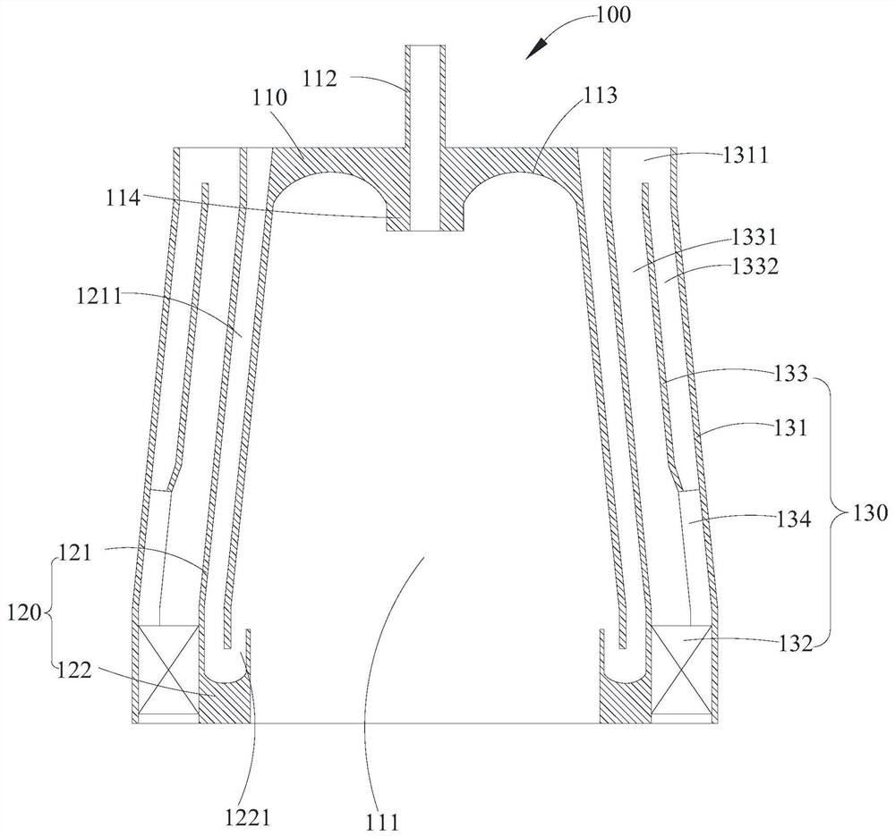
The invention provides an annular wall-heating type reverse injection pulverized coal burner, comprising: a pre-combustion structure, the pre-combustion structure has a preheating combustion chamber and a central ejection air pipe communicating with the preheating combustion chamber; a reverse injection The assembly includes a main pulverized coal pipe and a grooved retaining ring. The main pulverized coal pipe is sheathed on the outside of the pre-combustion structure and surrounds the main pulverized coal flow channel. The grooved retaining ring is connected to the The end of the main pulverized coal pipe is partly located at the outlet end of the pre-combustion structure, and the groove-shaped retaining ring and the end of the pre-combustion structure are surrounded by a reverse injection channel; and the secondary air assembly , including a secondary air pipe and a hollow opening blade, the secondary air pipe is sleeved on the outside of the main pulverized coal pipe, and is surrounded with the main pulverized coal pipe to form a secondary air channel, the hollow opening The rotary vane is arranged at the outlet end of the secondary air passage. There are no other pipelines and auxiliary structures inside the preheating combustion chamber, which makes the structure of the annular wall heat reverse injection pulverized coal burner simple and reliable in operation.

Description

technical field [0001] The invention relates to the technical field of pulverized coal combustion equipment, in particular to an annular wall-heating reverse injection pulverized coal burner. Background technique [0002] With the continuous development of pulverized coal processing and combustion utilization technology, for the suspension combustion method of air-carrying pulverized coal, due to the strengthening of the mutual contact and mixing between the gas and solid phases, it can improve the boiler combustion compared with the layer combustion combustion method. It has great advantages in terms of efficiency and thermal efficiency. Compared with large power plant boilers, the furnace size of industrial boilers is smaller, which greatly reduces the residence time of pulverized coal in the furnace, and in order to prolong the residence time of pulverized coal in industrial boilers, and at the same time promote the The timely heating and ignition of industrial boilers o...

Claims


Application Information

Patent Timeline
Patent Type & Authority Patents(China)
IPC IPC(8): F23D1/02F23N1/04
CPCF23D1/02F23N1/04F23D1/00F23D2201/00F23C2900/03005F23C2900/03006F23C5/12F23C7/004F23C2900/03003F23C9/003F23K1/04F23L15/04F23C7/06Y02E20/34F23C5/08F23C9/006
Inventor 李水清宋民航黄骞马鹏
Owner TSINGHUA UNIV
Learn More