Pervious template cloth permeability test method and device based on concrete slurry medium
A technology for permeable formwork cloth and concrete slurry, which is used in measurement devices, permeability/surface area analysis, suspension and porous material analysis, etc.
- Summary
- Abstract
- Description
- Claims
- Application Information
AI Technical Summary
Problems solved by technology
Method used
Image
Examples
Embodiment 1
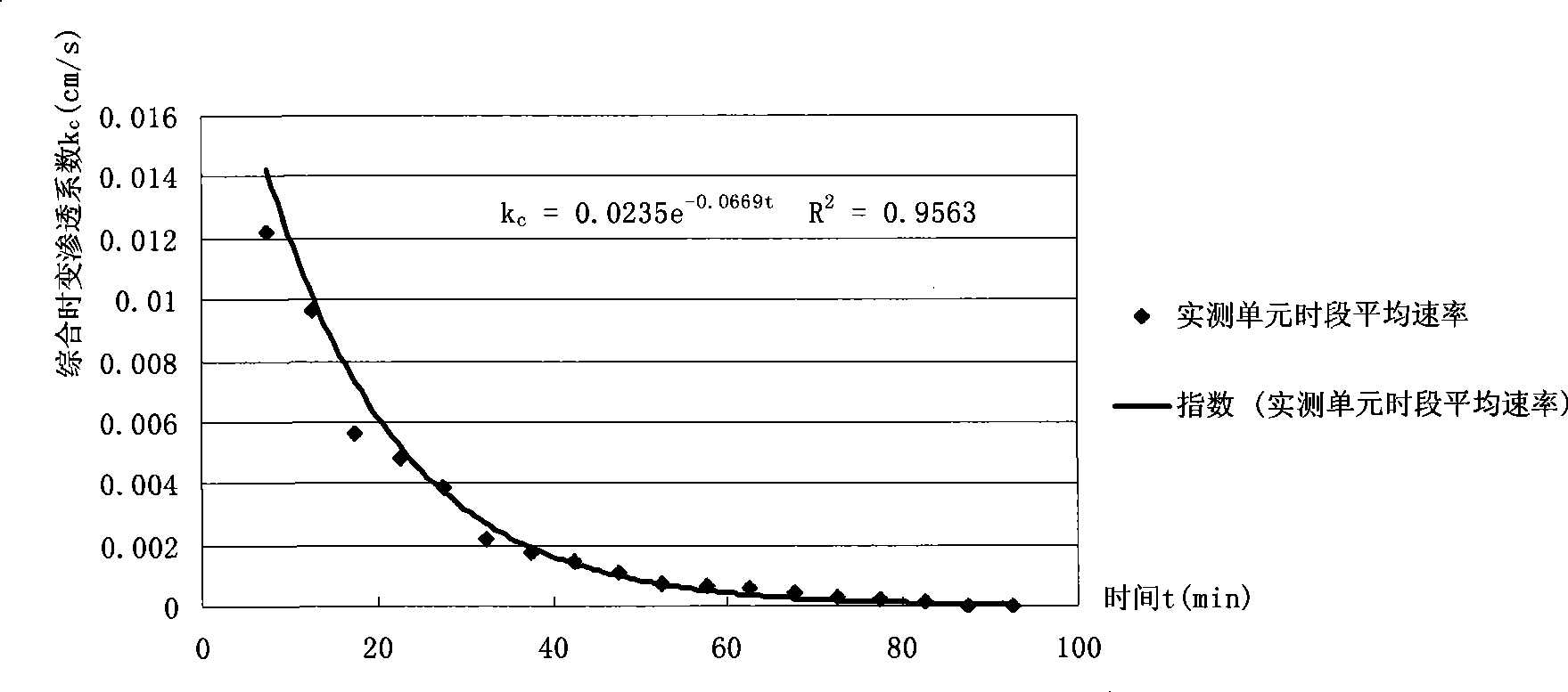
[0036] To test a brand of permeable formwork cloth, the mix ratio of the test concrete configured is as follows: cement: sand: stone: water: fly ash: JM-9 water reducing agent = 1:1.44:2.45:0.486:0.204:0.006; The lateral pressure applied to the sample is 4Kpa; the sample area is 30mm×0.113mm=3.39cm 2 ; Then the following data table 1 can be tested:
[0037] Table 1: Statistics of sample seepage discharge (Q) in each unit period of actual measurement
[0038] Serial number of continuous test time period 1 2 3 4 5 6 7 8 9 Infiltration water volume per unit period (ml) 41.28 32.58 19.02 16.32 13.02 7.38 5.94 4.98 3.66 Serial number of continuous test time period 10 11 12 13 14 15 16 17 18 Infiltration water volume per unit period (ml) 2.58 2.28 1.86 1.44 0.9 0.66 0.42 0.12 0.06
[0039] Note: The period of each test unit is 5 minutes, and the cumulative continuous test is 18*5=90 minutes.
[0040] Calculate accord...
Embodiment 2
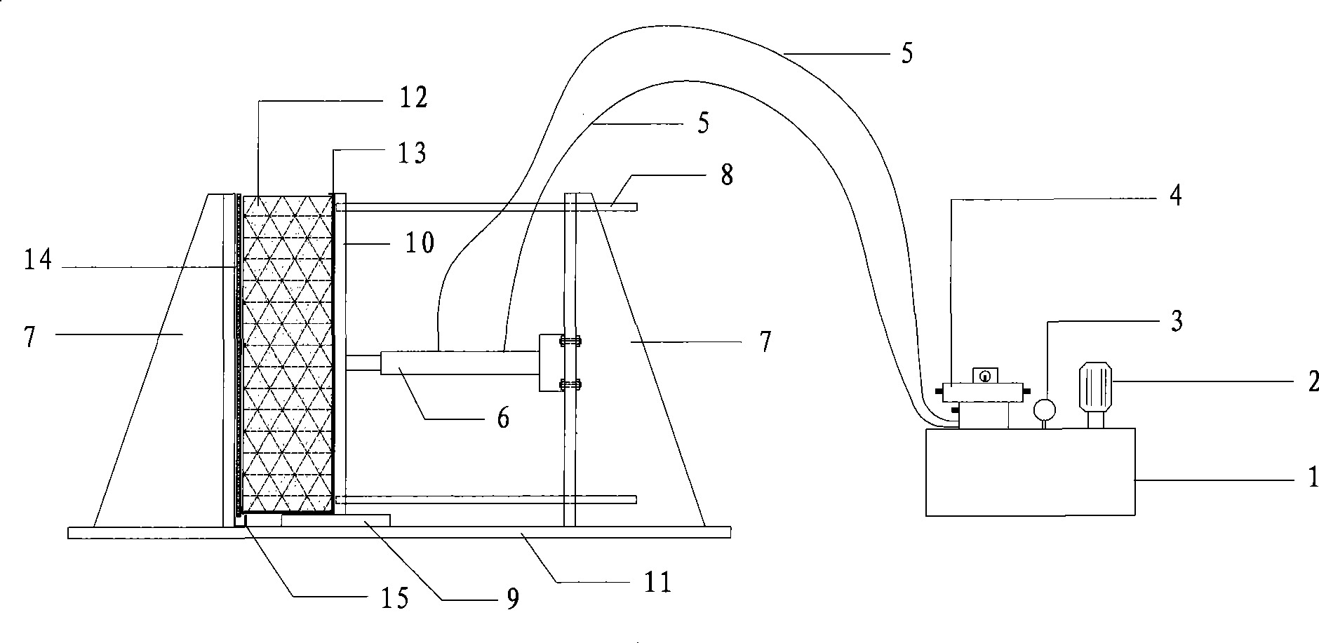
[0061] A device used in the permeable template cloth permeability test method based on concrete slurry medium, the device includes a pressurizing device, a counterforce support 7, a guide rod 8, a guide rail 9, a pressure plate 10 and a base plate 11. The reaction force support 7 is arranged vertically on the left and right sides of the base plate 11 respectively. On the base plate 1, a water collection tank 15 is provided on the inner side of the left reaction force support 7, and a pressure plate 10 is provided on the inner side of the right reaction force support. The base plate 11 is provided with a guide rail 9, the pressurizing device is located between the pressurizing plate 10 and the right reaction force support 7, the pressurizing plate 10 is connected with the right reaction force support 7 through the guide rod 8, and the pressurizing plate 10 passes through the guide The rod 8 moves horizontally between the counter force brackets 7 along the guide rail 9 arranged o...
PUM
 Abstract
Description
Claims
Application Information
 - R&D
- Intellectual Property
- Life Sciences
- Materials
- Tech Scout
- Unparalleled Data Quality
- Higher Quality Content
- 60% Fewer Hallucinations
Browse by: Latest US Patents, China's latest patents, Technical Efficacy Thesaurus, Application Domain, Technology Topic, Popular Technical Reports.
© 2025 PatSnap. All rights reserved.Legal|Privacy policy|Modern Slavery Act Transparency Statement|Sitemap|About US| Contact US: help@patsnap.com


