Composite material laying track micro diameter-changing self-regulating method
A technology of laying trajectory and adjustment method, which is applied in the direction of electrical program control and digital control, and can solve the problems of easy overlap or separation of layers
- Summary
- Abstract
- Description
- Claims
- Application Information
AI Technical Summary
Problems solved by technology
Method used
Image
Examples
specific Embodiment approach 1
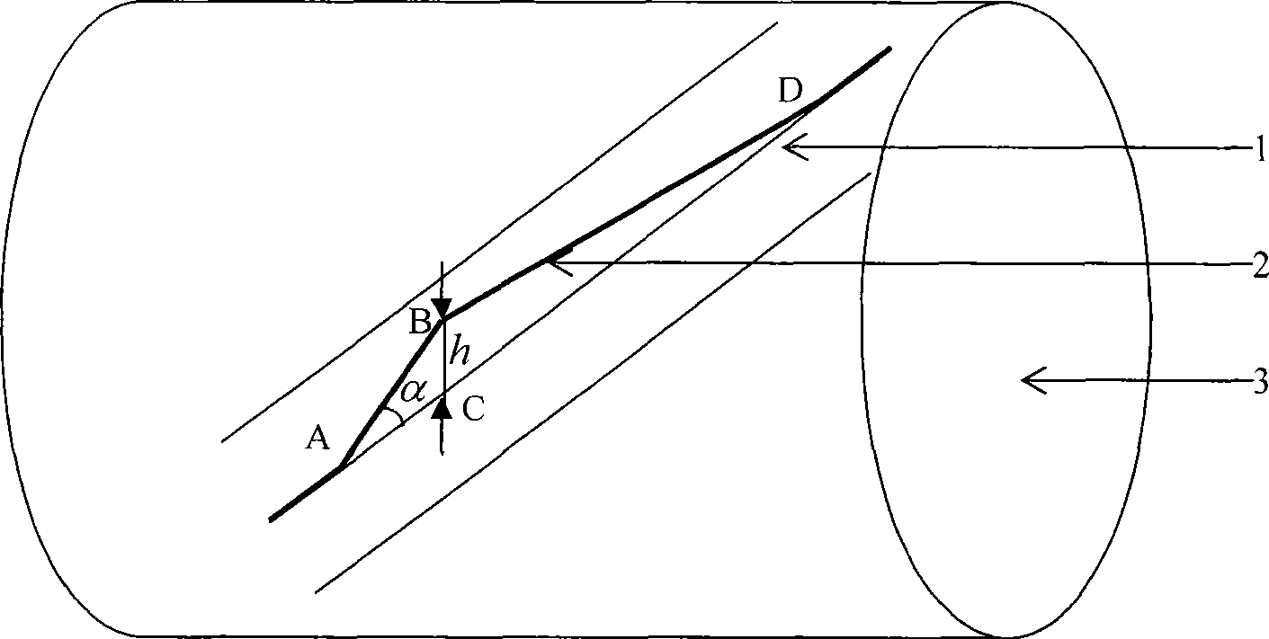
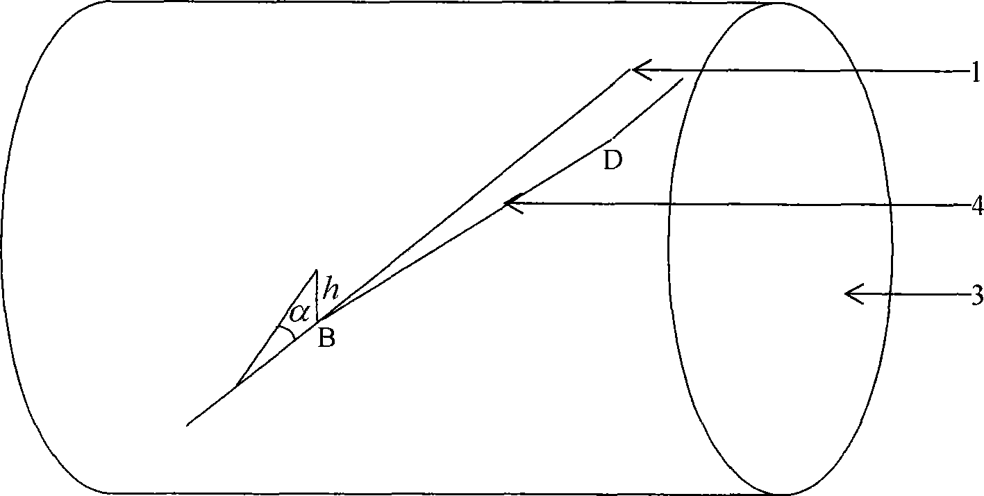
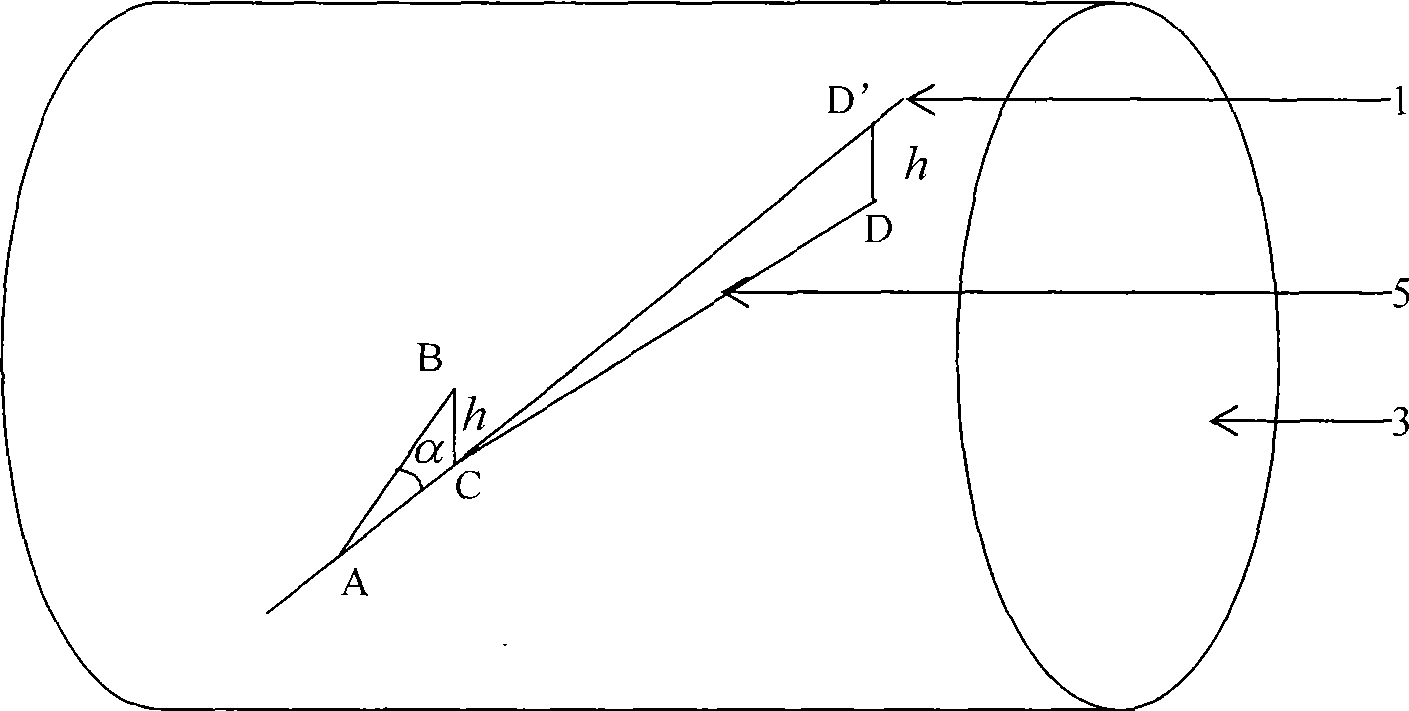
[0023] Specific implementation mode one: combine figure 1 , figure 2 with image 3 Describe this embodiment, this embodiment is composed of ideal laying trajectory curve 1, design trajectory curve 2, mandrel 3, single-step correction trajectory curve 4, correction trajectory curve 5; design the ideal laying trajectory on the surface of mandrel 3 according to working conditions Curve 1, laying trajectory 2 is designed after gridding the mandrel, if there is a deviation h between the design trajectory 2 and the ideal trajectory 1, see figure 1 , the design trajectory 2 needs to be slightly changed to eliminate the error processing; when the machine tool runs to point B, adjust the Y coordinate of the machine tool to the opposite direction of the design trajectory deviation h to ensure the accuracy of the trajectory of the AB section, see figure 2 ; There is a stable deviation h in the adjusted corrected trajectory BD, so it is necessary to make a second adjustment to traject...
specific Embodiment approach 2
[0024] Specific implementation mode two: combination Figure 4 , Figure 5 with Image 6 Describe this embodiment, this embodiment is composed of ideal laying trajectory curve 1, design trajectory curve 2, mandrel 3, single-step correction trajectory curve 6, and correction trajectory curve 7; design the ideal laying trajectory on the surface of mandrel 3 according to working conditions Curve 1, laying trajectory 2 is designed after gridding the mandrel, if there is a deviation h1 between the design trajectory 2 and the ideal trajectory 1, see Figure 4 , the design trajectory 2 needs to be micro-varied to eliminate the error processing; when the machine tool runs to point B, adjust the laying head of the machine tool to the opposite direction of the design trajectory deviation to adjust h1 to ensure the accuracy of the AB segment trajectory, see Figure 5 ; There is a stable deviation h1 in the adjusted corrected trajectory BD, so it is necessary to make a second adjustment...
specific Embodiment approach 3
[0025] Specific implementation mode three: combination Figure 7 , Figure 8 with Figure 9 Describe this embodiment, this embodiment is composed of ideal laying trajectory curve 1, design trajectory curve 2, mandrel 3, single-step correction trajectory curve 8, and correction trajectory curve 9; design the ideal laying trajectory on the surface of mandrel 3 according to working conditions Curve 1, laying trajectory 2 is designed after gridding the mandrel, if there is a deviation h2 between the design trajectory 2 and the ideal trajectory 1, see Figure 7 , the design trajectory 2 needs to be slightly changed to eliminate the error processing; when the machine tool runs to point B, adjust the X coordinate of the machine tool to the opposite direction of the design trajectory deviation h2 to ensure the accuracy of the trajectory of the AB segment, see figure 2 ;There is a stable deviation h2 in the adjusted corrected trajectory BD, so the trajectory 8 needs to be adjusted t...
PUM
 Abstract
Description
Claims
Application Information
 - R&D
- Intellectual Property
- Life Sciences
- Materials
- Tech Scout
- Unparalleled Data Quality
- Higher Quality Content
- 60% Fewer Hallucinations
Browse by: Latest US Patents, China's latest patents, Technical Efficacy Thesaurus, Application Domain, Technology Topic, Popular Technical Reports.
© 2025 PatSnap. All rights reserved.Legal|Privacy policy|Modern Slavery Act Transparency Statement|Sitemap|About US| Contact US: help@patsnap.com


