Subdivision solar water heater
A solar water heater and subdivision technology, applied in the field of solar energy utilization, can solve problems such as the drop of hot water temperature and the reduction of hot water utilization rate, and achieve the effects of improving efficiency, overcoming low installation position and improving utilization rate.
- Summary
- Abstract
- Description
- Claims
- Application Information
AI Technical Summary
Problems solved by technology
Method used
Image
Examples
Embodiment 1
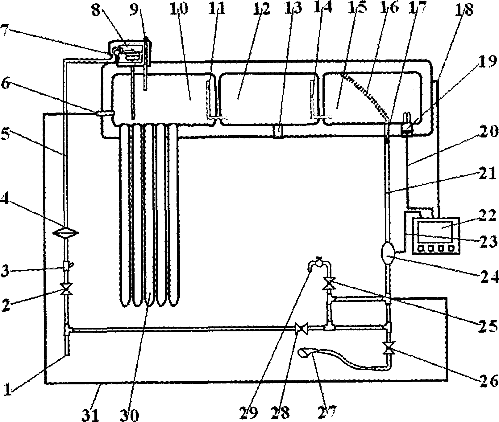
[0044] The tap water inlet pipe 1 of the present invention communicates with the water inlet cabin 10 through the temperature difference forced circulation water pipe 5 and the cold water inlet 7 , and leads into the lower part of the inner cavity of the water inlet cabin 10 .
[0045] The above structure ensures that the cold water that has just entered the water inlet cabin 10 is at the bottom of the inner cavity of the water inlet cabin 10, and the original relatively hot water in the water tank is pushed up and flows to the warm water cabin 12, instead of allowing the cold water to flow directly to the warm water cabin 12 .
Embodiment 2
[0047] The hot water pipe 21 of the present invention communicates with the hot water tank 15 through the water outlet 17 , and the water outlet 17 is arranged at the bottom of the hot water tank 15 . The hot water tank 15 is provided with a hose-shaped hot water tracker 16 , one port of which communicates with the water outlet 17 , and the other port floats on the upper part of the inner cavity of the hot water tank 15 .
[0048] The effect of the hot water tracker 16 is: when the water temperature was low, the height of its port floating was higher, so that the temperature of the flowing water was as high as possible; when the water temperature was higher, the height of its port floating was lower, The temperature of the outflowing water is lowered appropriately, because at this time it can obtain low-temperature water from the lower water inlet. Therefore, the water outlet 17 is arranged at the bottom of the hot water tank 15, so that the hot water tracker 16 can float acco...
Embodiment 3
[0050] According to the present invention, the hot water deflector 11 communicated with the water inlet cabin 10 and the warm water cabin 12 has a port at one end arranged at the upper part of the inner cavity of the water inlet cabin 10, and the other end is arranged at the lower part of the inner cavity of the warm water cabin 12; The hot water flow deflector 14 communicated with the warm water cabin 12 and the hot water cabin 15 has a port at one end arranged at the upper part of the inner cavity of the warm water cabin 12, and the other end is arranged at the lower part of the inner cavity of the hot water cabin 15.
[0051] The above-mentioned setting method of the hot water deflector 11 ensures that hot water is discharged from the top of each water tank, and cold water enters from the bottom of each water tank, slowing down the mixing speed of cold and hot water.
PUM
 Abstract
Description
Claims
Application Information
 - R&D
- Intellectual Property
- Life Sciences
- Materials
- Tech Scout
- Unparalleled Data Quality
- Higher Quality Content
- 60% Fewer Hallucinations
Browse by: Latest US Patents, China's latest patents, Technical Efficacy Thesaurus, Application Domain, Technology Topic, Popular Technical Reports.
© 2025 PatSnap. All rights reserved.Legal|Privacy policy|Modern Slavery Act Transparency Statement|Sitemap|About US| Contact US: help@patsnap.com

