Surface treatment installation for metallic parts, particularly by electrolysis

A technology for processing equipment and metal components, which is applied to electrolytic components, electrolytic processes, electrodes, etc., and can solve problems such as damage to batch components

Inactive Publication Date: 2009-05-06
TORNOS MANAGEMENT HLDG
View PDF3 Cites 5 Cited by
  • Summary
  • Abstract
  • Description
  • Claims
  • Application Information

AI Technical Summary

Problems solved by technology

The disadvantage of this method is that the rota

Method used


Image

  • Surface treatment installation for metallic parts, particularly by electrolysis
  • Surface treatment installation for metallic parts, particularly by electrolysis
  • Surface treatment installation for metallic parts, particularly by electrolysis

Examples


Embodiment Construction

[0021] [21] According to the method of implementation of the treatment plant according to the invention, each member is immersed in the tank and subjected to at least a rotational movement, so that air bubbles that may have formed in the electrolytic cell are discharged from the inner wall of said member.

[0022] [22] According to the embodiment shown, each member is subjected to a rotational movement of at least 90°, preferably 360°.

[0023] [23] According to the embodiment shown, a defined number of said components is placed beforehand on a support or box 4 having at least one retainer for each of said components. mechanism.

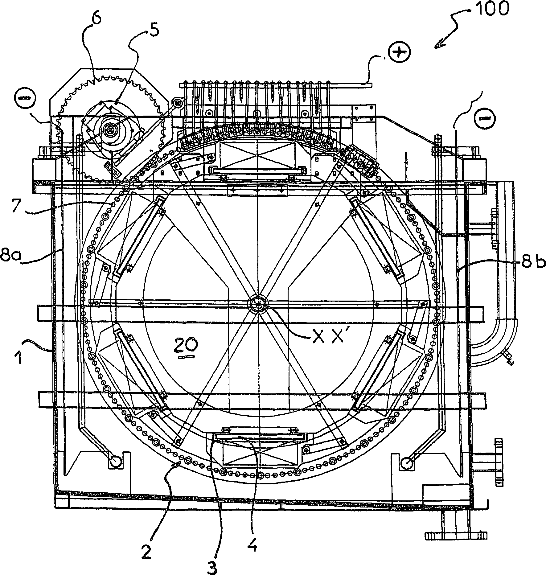
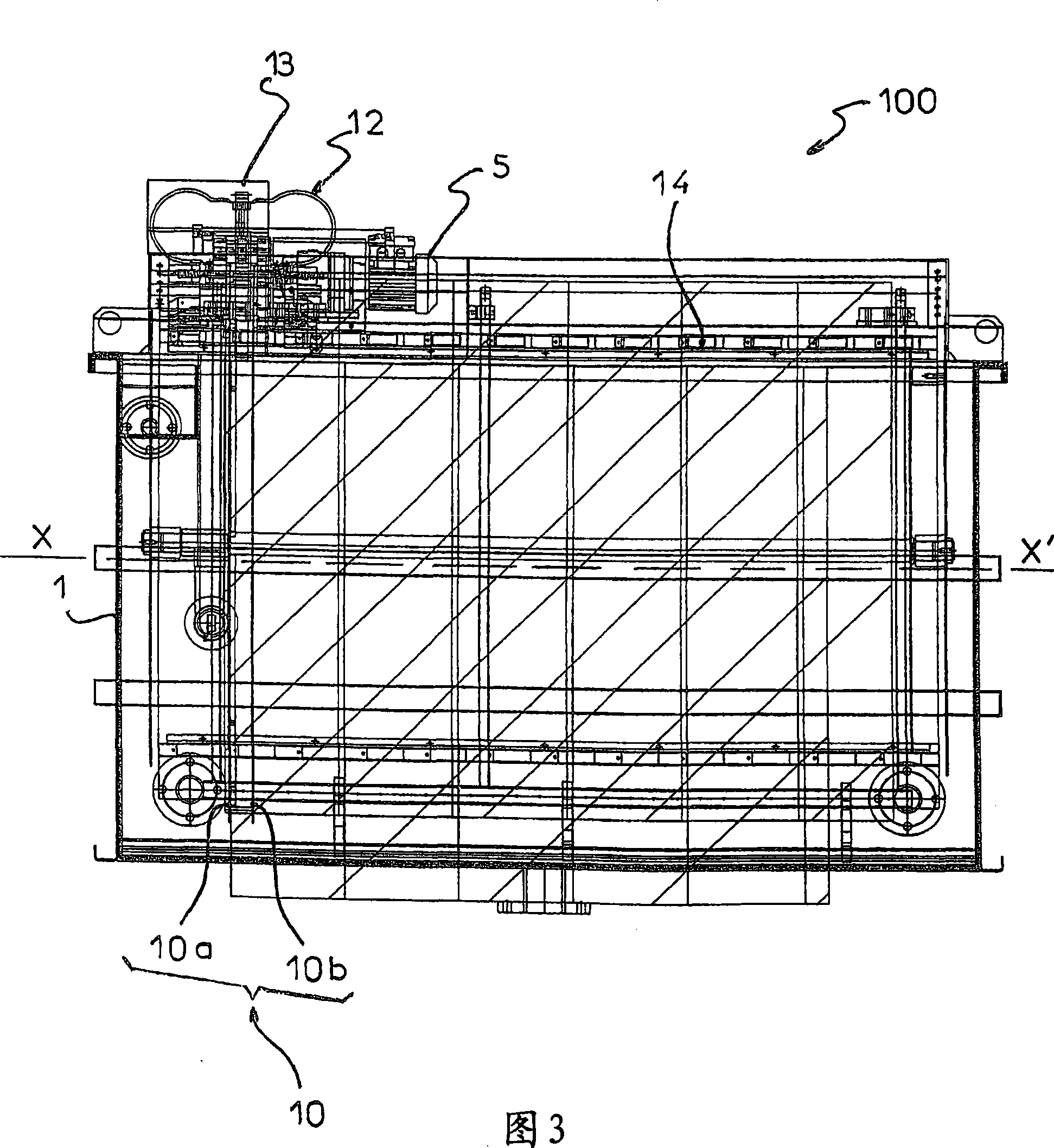
[0024] [24] According to this embodiment, the component treatment plant bearing the general reference numeral 100 comprises a tank 1 having a drum 2 inside the tank 1 along a horizontal axis X, X 'rotatably mounted, the component to be treated is fixed on said drum 2.

[0025] [25] According to the embodiment shown, the drum 2 has on its outer peri...


PUM


Abstract

Surface treatment installation (100) for metallic parts including an electrolytic cell (1) comprising a treatment liquid (20) in which the parts to be treated are immersed, characterised in that the parts to be treated are fixed on a pivoting drum (2) such that there is at least one rotation movement for each part in the cell, and in that the cell (1) comprises at least two electrodes (8a, 8b), while the drum is powered by an electrical power supply with polarity opposite to the electrode polarity, through at least one contact pad that is brought into contact on the drum drive ring.

Description

technical field [0001] [01] The present invention relates to improvements in methods of electrolytic surface treatment of metal components, and more particularly to continuous electrolytic cells using the principle of component immersion and transport. Background technique [0002] [02] The electrolytic surface treatment of components is a known method which requires the use of an electric current to carry out the treatment. [0003] [03] Electrolysis can be applied to metals such as anodic treatment of aluminum, anion electrophoresis for electrolytic deposition of coatings on aluminum, treatments on steel such as zinc plating, chrome plating, copper plating, nickel plating, cationic electrophoresis, treatment with phosphates, copper treatment Such as tin plating, but also can be applied to electrolytic deposition on non-metallic components, such as electroplating of plastic components. [0004] [04] According to the traditional electrolysis method, the member to be treated...

Claims


Application Information

Patent Timeline
IPC IPC(8): C25D17/02C25D17/12C25D17/18
CPCC25D7/04C25D17/28C25D17/20C25D17/02C25D17/12
Inventor F·瓦谢龙
Owner TORNOS MANAGEMENT HLDG
Why Eureka
Try Eureka