Clutch unit

A technology of clutches and side clutches, applied in the direction of clutches, one-way clutches, mechanically driven clutches, etc., which can solve the problem of large elastic deformation, reducing the strength of the outer ring 114 on the control rod side and the outer ring 122 on the braking device side, and difficult to improve damage Torque and other issues, to achieve the effect of increasing strength, increasing breaking torque, and reducing elastic deformation

Active Publication Date: 2012-12-12
NTN CORP
View PDF2 Cites 0 Cited by
  • Summary
  • Abstract
  • Description
  • Claims
  • Application Information

AI Technical Summary

Problems solved by technology

That is, it is difficult to produce the lever-side outer ring 114 and the brake device-side outer ring 122 by press working from a plate-shaped material having a thickness greater than a certain value.
[0013] Therefore, the plate thicknesses of the lever-side outer ring 114 and the brake device-side outer ring 122 had to be reduced. As a result, the strength of the lever-side outer ring 114 and the brake device-side outer ring 122 was reduced. Large, it is difficult to increase the breaking torque as a clutch

Method used


Image

  • Clutch unit
  • Clutch unit
  • Clutch unit

Examples


Embodiment Construction

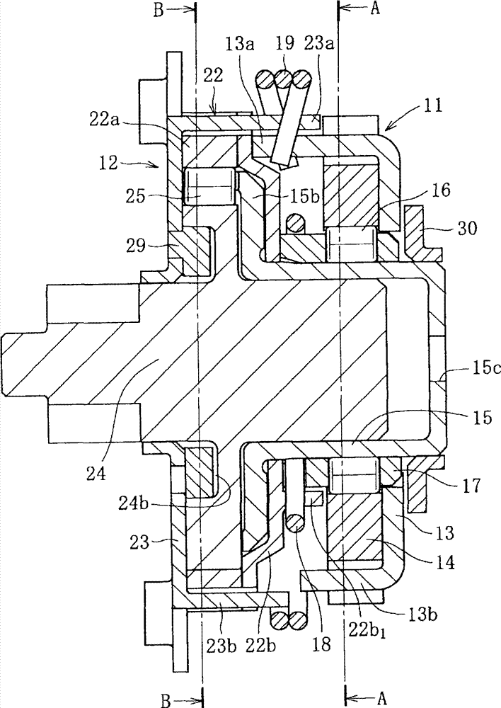
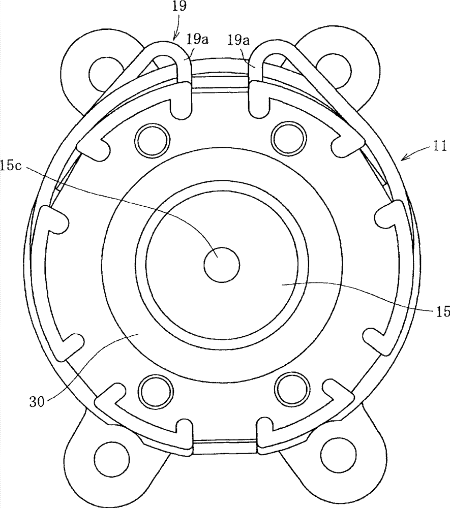
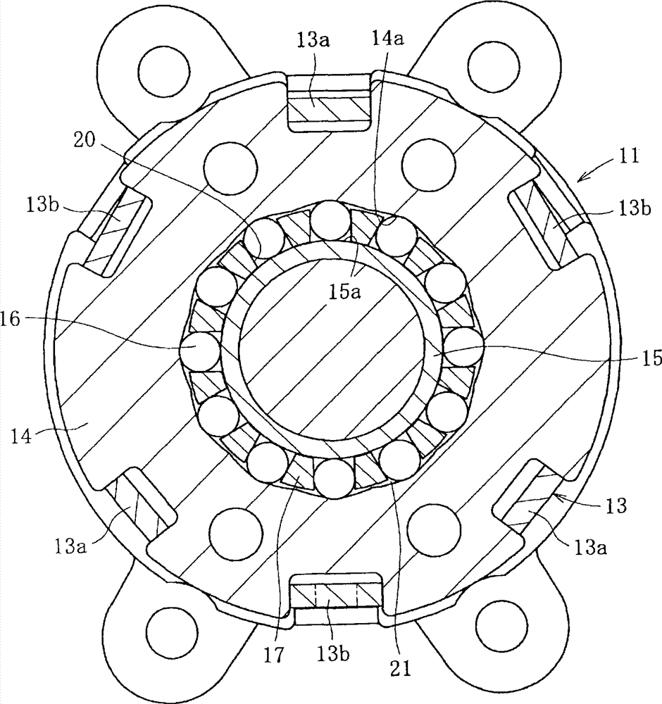
[0043] figure 1 It is a sectional view showing the overall structure of a clutch unit according to an embodiment of the present invention, figure 2 yes figure 1 right side view of the image 3 is along figure 1 The sectional view of the line A—A, Figure 4 is along figure 1 The sectional view of the B-B line.

[0044] This clutch unit includes: a lever side clutch part 11 provided on the input side; and a brake device side clutch part 12 provided on the output side with an opposite input blocking function.

[0045] The lever-side clutch unit 111 includes, for example, a lever-side outer ring 14 as an input-side member to which a lever (not shown) is connected; an inner ring 15 as a connecting member; and, for example, a plurality of cylindrical rollers as engagement members. 16. A retainer 17 for holding the cylindrical roller 16; an inner return spring 18 as a first elastic member for returning the retainer 17 to a neutral state; a function for returning the lever ...


PUM


Abstract

Provided is a clutch unit in which the strength of a lever side outer ring or a brake side outer ring is increased and in which an elastic deformation amount is reduced to help to easily achieve an improvement in terms of breaking torque. The clutch unit has a lever side clutch section (11) provided on an input side, for controlling transmission and interrupting rotational torque to an output side through lever operation, and also has a brake side clutch section (12) provided on the output side, for transmitting input torque from the lever side clutch section (11) to the output side and interrupting reverse input torque from the output side. A lever side outer ring (22) of the brake side clutch section (12) is formed with two members of a thick plate-like member (22a) formed by punching and a cover (22b) formed by press working. The plate-like member (22a) and the cover (22b) are integrally fixed together by swaging by means of a lever-side side plate (23). A lever side outer ring (14) of the lever side clutch section (11) is formed of a thick plate-like member formed by punching.

Description

technical field [0001] The present invention relates to a lever-side clutch unit that transmits rotational torque from the input side to the output side, and transmits the rotational torque from the input side to the output side, and blocks opposite input torque from the output side. The clutch unit of the brake device side clutch unit. Background technique [0002] Generally, in a clutch unit using an engaging member such as a cylindrical roller or a ball, a clutch portion is provided between an input side member and an output side member, but the clutch portion passes between the input side member and the output side member. The wedge gap formed between them engages and disengages engaging parts such as cylindrical rollers or balls to control the transmission and isolation of input torque. [0003] This type of clutch unit includes: a seat lifter for a car that can be adjusted up and down by operating a lever; a lever-side clutch that transmits rotational torque from the ...

Claims


Application Information

Patent Timeline
Patent Type & Authority Patents(China)
IPC IPC(8): F16D15/00F16D41/08F16D47/04
CPCF16D41/105
Inventor 川合正浩
Owner NTN CORP
Why Eureka
Try Eureka