Speed response type damper and shock-absorbing damper device

A damper and speed technology, applied in the direction of shock absorbers, shock absorbers, springs/shock absorbers, etc., can solve problems such as working fluid bubbles, damage to left and right balance, piston rod tilting, etc., to eliminate sudden changes in repulsive force , Improve the rectification effect, eliminate the effect of the inclination of the piston rod

Active Publication Date: 2009-05-06
NIFCO INC
View PDF1 Cites 9 Cited by
  • Summary
  • Abstract
  • Description
  • Claims
  • Application Information

AI Technical Summary

Problems solved by technology

[0004] However, in the cylinder-type oil-piston damper with the above structure, air bubbles may be generated in the working fluid when the load applied to the rod suddenly changes after changing a part of the cylinder bore.
Bubbles in the working fluid will destroy the left-right balance and cause the piston rod to tilt
in addition, Figure 14 In the oil damper shown, there are problems such as that the generated air bubbles will burst after passing through the flow hole 3 of the piston 2 and make a crackling sound.

Method used


Image

  • Speed response type damper and shock-absorbing damper device
  • Speed response type damper and shock-absorbing damper device
  • Speed response type damper and shock-absorbing damper device

Examples


Embodiment Construction

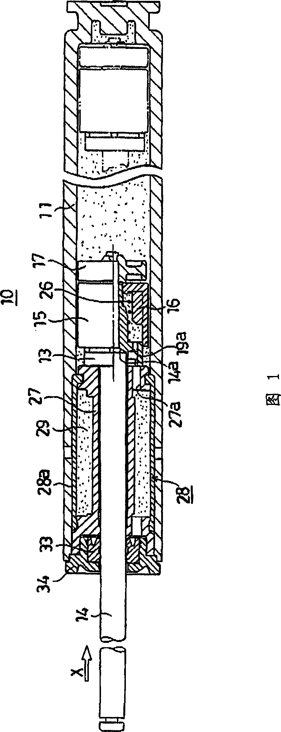
[0036] In the present invention, an orifice is provided on the top end side of the piston, and air rupture occurs in the annular portion of the piston, so the cracking sound can be reduced, and the inner circumference of the slider that can adjust the amount of fluid passing through the piston has a plurality of rectifying protrusions. Therefore, sudden changes in repulsive force and tilting of the piston rod can be prevented during high-speed operation.

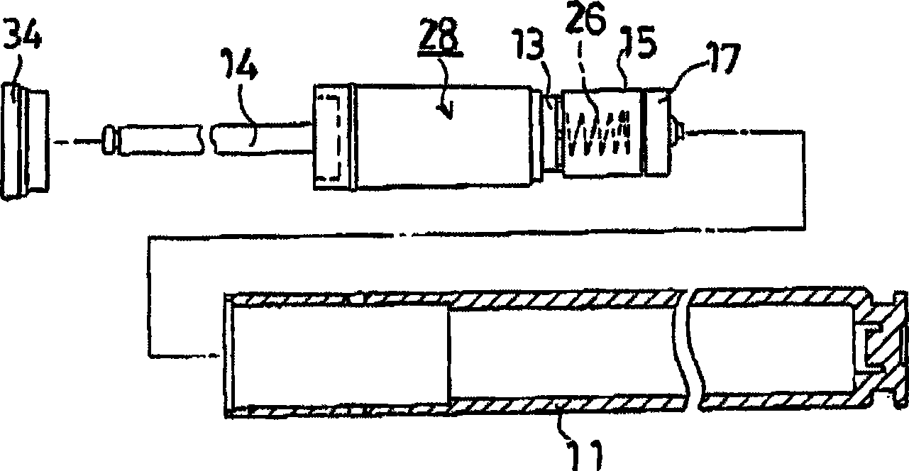
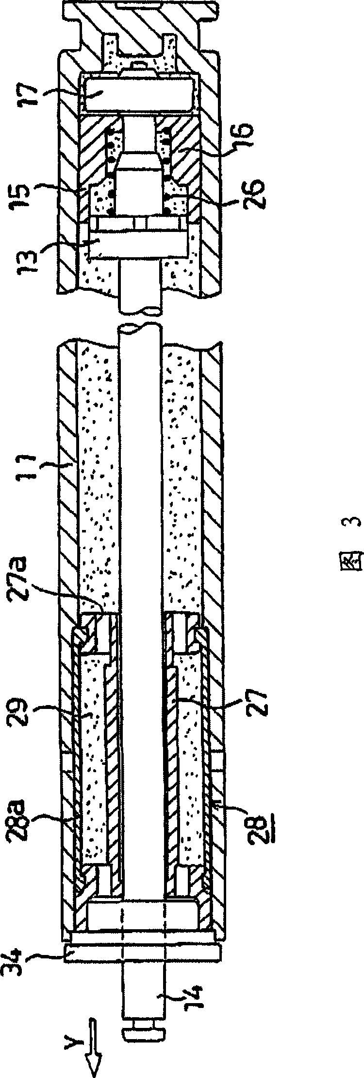
[0037] Hereinafter, the present invention will be described in detail based on the drawings showing an embodiment. FIG. 1 is a cross-sectional view showing the overall structure of a speed-responsive damper according to the present invention, figure 2 FIG. 3 is an exploded view showing an example of the speed responsive damper of the present invention, and FIG. 3 is a cross-sectional view showing an operating state of the speed responsive damper of the present invention. Here, the speed-responsive damper 10 has a cylinder ...


PUM


Abstract

A speed responsive damper (10) comprises a cylinder (11) in which a fluid is filled, a piston (13) slidably fitted into the cylinder and having an orifice (19a) through which the fluid passes, a piston rod (14) having one end fixed to the piston and the other end extended to the outside of the cylinder, and a slider (15) which is disposed in the cylinder and movable in a predetermined range relative to the piston, and regulates the amount of the fluid passing through the piston. Since the orifice is formed at the end of the piston, explosive noise of air can be lowered, swirl and slip of oil can be prevented from occurring, and the piston rod can be prevented from being tilted.

Description

technical field [0001] The present invention relates to a cylinder type oil damper, especially relates to a speed response type damper which reduces the cracking sound of air passing through an orifice and does not generate a sharp repulsive force when the piston is displaced at high speed, and a shock absorbing damper using the damper. Background technique [0002] In general, a cylinder-type oil piston damper proposes a structure in which a part of the cylinder inner diameter is changed in order to change the repulsive force. For example, the damper disclosed in Japanese Patent Application Laid-Open No. 2004-28167 has a structure of: enlarging the inner diameter of the end of the cylinder to form a diameter-expanding part, and a repulsive spring with a large elastic force is arranged in the diameter-expanding part. When the piston reaches the diameter-expanding part, The repulsive force is obtained from the elastic force. [0003] Figure 14 In the shown oil damper, the o...

Claims


Application Information

Patent Timeline
Patent Type & Authority Applications(China)
IPC IPC(8): F16F9/50E05F5/00E05F5/10F16F9/32
CPCF16F9/3214E05F5/003F16F9/065F16F9/3228F16F9/3405F16F9/5126E05Y2201/256E05F5/10E05Y2201/264E05Y2201/21F16F9/32F16F9/58
Inventor 富田重光
Owner NIFCO INC
Why Eureka
Try Eureka