
An electronic driver for a fluorescent lamp

A technology for electronic drivers and fluorescent lamps, applied to light sources, electric light sources, electrical components, etc., can solve the problems of high power consumption of inductors, low circuit frequency, and high cost, and achieve adjustable warm-up time, increased circuit power, and light weight Effect

Inactive Publication Date: 2013-02-20
禤伟旗 +2
View PDF0 Cites 1 Cited by
  • Summary
  • Abstract
  • Description
  • Claims
  • Application Information

AI Technical Summary

Problems solved by technology

Fluorescent lamp itself is a mature product, but its driving circuit used in the past application has low circuit frequency, large inductor power consumption, low efficiency and high cost

Method used


Image

  • An electronic driver for a fluorescent lamp
  • An electronic driver for a fluorescent lamp
  • An electronic driver for a fluorescent lamp

Examples


Embodiment Construction

[0023] The electronic driver for fluorescent lamps provided by the present invention will be described below in conjunction with a specific embodiment. It should be understood by those skilled in the art that the specific embodiments in the specification are intended to be examples rather than specific limitations on the present invention.

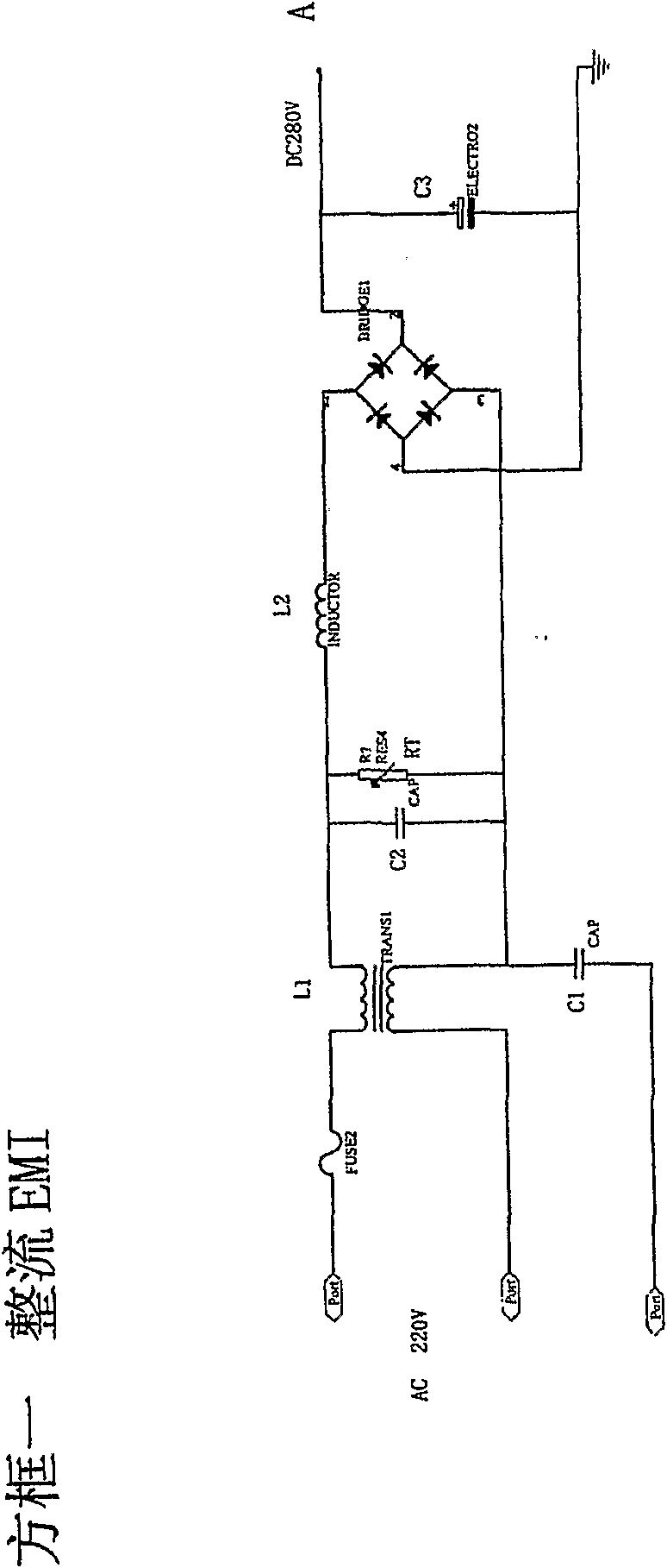
[0024] Fig. 1 is an overall circuit block diagram of an embodiment of an electronic driver for fluorescent lamps according to the present invention, including functional block 1, functional block 2, functional block 3 and their connections.

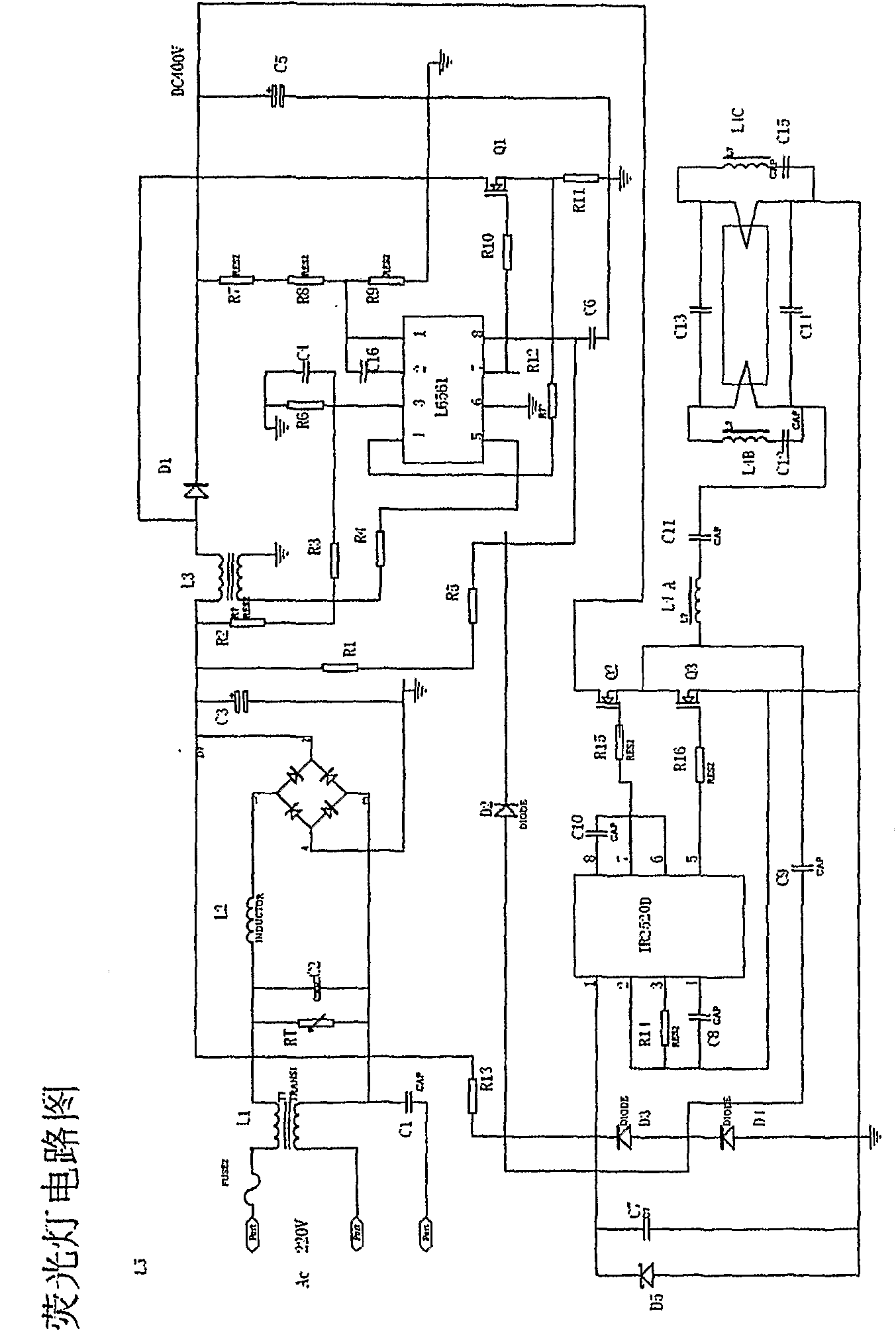
[0025] According to an embodiment of the present invention, FIG. 2 is an overall circuit diagram of an electronic driver for a fluorescent lamp.

[0026] The following description of the circuit diagram focuses on some content related to the technical problems or technical effects of the present invention, and some other specific details not involved in the following description should be understood b...


PUM


Abstract

The present invention relates to an electric driver for fluorescent lamp, comprising an input circuit for rectifying and filtering an inputted alternating voltage with certain amplitude and a power factor correction circuit for further amplifying the voltage rectified and filtered by the input circuit to obtain a stable DC voltage with higher amplitude. The electric driver further comprises an output circuit for receiving the DC voltage outputted from the power factor correction circuit as its operating power supply, and providing the fluorescent lamp with an output without input transformer and without output transformer.

Description

technical field [0001] The present invention relates to an electronic driver, in particular to an electronic driver for fluorescent lamps. Background technique [0002] Fluorescent lamp is a kind of high-pressure gas discharge lamp, which is widely used in people's daily life because of its good brightness, no flicker, long life and energy saving. Such as industry, agriculture, streets, exhibition centers, square parking lots, industrial and mining enterprises, large clubs, etc. [0003] At present, the world is facing more and more serious energy shortages, and it is urgent to require people to save energy in daily life and public facilities. Fluorescent lamp itself is a mature product, but its drive circuit used in the past has a low circuit frequency, large inductor power consumption, low efficiency and high cost. Therefore, for a long time, people hope to obtain an electronic driver for fluorescent lamps with energy saving, high efficiency, wide input voltage operating...

Claims


Application Information

Patent Timeline
Patent Type & Authority Patents(China)
IPC IPC(8): H05B41/295
CPCY02B20/183H05B41/282Y02B20/00H05B41/14H05B41/24
Inventor 禤伟旗潘乐祺李云
Owner 禤伟旗
Learn More