Boost type digital control active power factor correction converter

A technology of digital control and source power, applied in the direction of output power conversion device, high-efficiency power electronic conversion, climate sustainability, etc., to achieve the effect of reducing high-frequency noise, increasing switching frequency, and being easy to implement

Inactive Publication Date: 2017-05-31
NANJING UNIV OF SCI & TECH
View PDF5 Cites 6 Cited by
  • Summary
  • Abstract
  • Description
  • Claims
  • Application Information

AI Technical Summary

Problems solved by technology

[0003] Because of these advantages, after decades of development, the analog control technology of power factor correction has become very mature with the wider application of power electronic products, but there are still some limitations

Method used


Image

  • Boost type digital control active power factor correction converter
  • Boost type digital control active power factor correction converter
  • Boost type digital control active power factor correction converter

Examples


Embodiment Construction

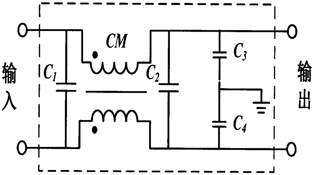
[0032] 1. EMI circuit

[0033] The basic circuit of EMI filter as figure 2 As shown, it is a simple single-stage filter, and the circuit includes common-mode inductor CM, differential-mode filter capacitors C1 and C2, and common-mode filter capacitors C3 and C4.

[0034] Function: EMI signal is a two-way interference signal. On the one hand, external interference can enter the electronic equipment from the power supply line; on the other hand, the electronic equipment will generate interference signals and transmit them out through the power line; is a noise source. Therefore, the EMI filter must also be designed to be bidirectional, not only to filter out the external electromagnetic interference introduced, but also to prevent the device itself from sending out interference signals to the outside. From the perspective of formation characteristics, interference signals are divided into two types: differential mode interference and common mode interference. Differential-mo...


PUM


Abstract

The present invention discloses a boost type digital control active power factor correction converter. The boost type digital control active power factor correction converter comprises an EMI circuit 1, a boost circuit 2 with a rectifier bridge, a sampling circuit 3, a digital control chip 4 and a drive circuit 5. The input of the EMI circuit 1 is an alternating current voltage, and the output is the input of the boost circuit 2 with the rectifier bridge. The sampling circuit 3 samples three analog quantities: a rectification input voltage V<in>, an inductance current I<L> and an output voltage V<0> in the boost circuit with the rectifier bridge. The three analog quantities sampled by the sampling circuit 3 are input into an analog-to-digital conversion module of the digital control chip 4. The input of the drive circuit 5 is a duty cycle signal PWM emitted by a PWM module in the digital control chip, and the output is connected with gate poles of two MOSFETs in the boost circuit with the rectifier bridge. Through adoption of the boost type digital control active power factor correction converter, the switch frequency is improved, the volume of the magnetic element is reduced, and the power density of the converter is improved.

Description

technical field [0001] The invention relates to the implementation of power factor correction in switching power supplies, especially through the digital active power factor correction (APFC) technology to realize single-phase power factor correction under small and medium power and three-phase power factor correction under high power. Background technique [0002] Significance of power factor correction in switching power supply: reducing harmonic content is beneficial to reduce interference to other electrical equipment, and the improvement of power factor is also worrying about improving the utilization rate of grid equipment and saving electric energy; after adopting PFC measures, the power supply The allowable input voltage range can be enlarged, which can reach 90-265V (single phase), which can adapt to different power grid voltages in various countries in the world, greatly improving the reliability and flexibility of the switching power supply; after taking PFC measur...

Claims


Application Information

Patent Timeline
Patent Type & Authority Applications(China)
IPC IPC(8): H02M1/42
CPCH02M1/4225Y02B70/10
Inventor 李强赵怀友宋俊超谭畅邵立伟
Owner NANJING UNIV OF SCI & TECH
Why Eureka
Try Eureka