Far-near light on-off mechanism for overtaking

A switch mechanism, far and near beam technology, applied in electrical switches, optical signals, vehicle components, etc., can solve the problems of single gear control, burnout of contacts, unsatisfactory wear resistance and repeatability of ejector pins, etc. The effect of expanding application space and improving stability

Inactive Publication Date: 2009-05-13
阮坚毅
View PDF0 Cites 10 Cited by
  • Summary
  • Abstract
  • Description
  • Claims
  • Application Information

AI Technical Summary

Problems solved by technology

[0003] Because the above structure adopts the push pin elastic mechanism to drive the movable contact piece to realize the switch, firstly, the wear resistance and repeatability of the push pin in practical application are not very ideal, which in turn affects the long-term reliability and stability of the entire switch, and is likely to cause contact point burn out; moreover,

Method used


Image

  • Far-near light on-off mechanism for overtaking
  • Far-near light on-off mechanism for overtaking
  • Far-near light on-off mechanism for overtaking

Examples


Embodiment

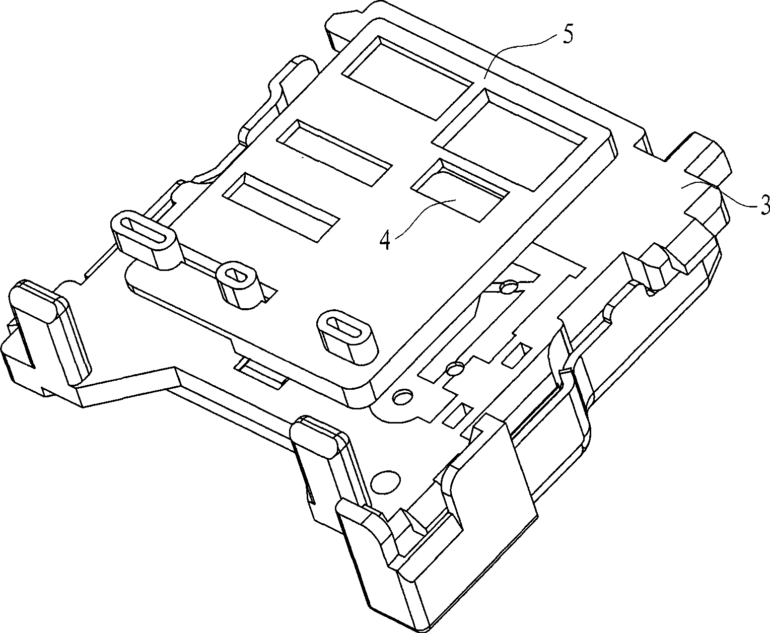
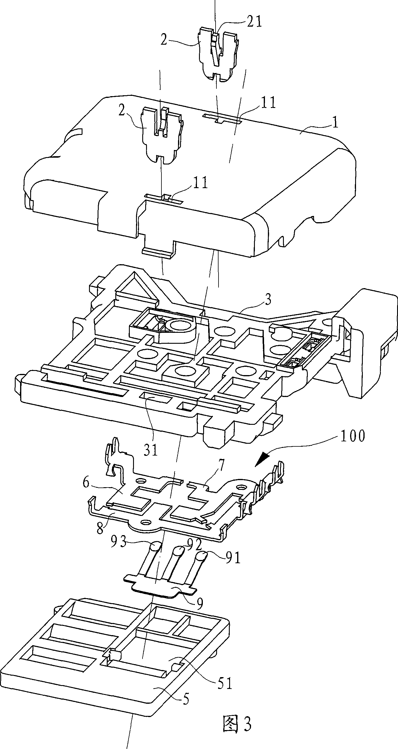
[0031] Example: Reference figure 1 , figure 2 , shown in Figure 3 and Figure 4, the high and low beam overtaking switch mechanism in the present embodiment includes a base 3, a slider 5, and a protective cover 1.

[0032] The protective cover 1 is arranged on the outer surface of the base 3, and the specific setting method is as follows: the opposite sides of the base 3 are respectively provided with snap-in holes 31, and the side of the protective cover 1 is protrudingly provided with snap-in ears that cooperate with the snap-in holes 31 12. There is an embedded hole 11 on the inner side of the protective cover 1, and the embedded block 2 is embedded in the embedded hole 11 to restrict the inward swing of the clip ear 12. Further, the clip ear 12 has an outwardly turned edge 121. Correspondingly, the clip The port of the connecting hole 31 has a blocking surface for the flap 121 to be hooked to limit the locking ear 12 from the locking hole 11. Further, in order to limit t...


PUM


Abstract

The utility model relates to a high-low beam overtaking switch mechanism which comprises a base (3), and a static contact piece (100) arranged on the base (3). The high-low beam overtaking switch mechanism is characterized in that the mechanism further comprises a sliding block (5) capable of sliding in relation to the base (3); the static contact piece (100) comprises a high beam contact piece (7), a grounding contact piece (6) and a headlamp contact piece (8) which are arranged in mutual independence; and a movable contact piece (9) in fit with the static contact piece (100) is arranged on the sliding block (5) and can move together with the sliding block (5). Compared with the prior art, the invention has the advantage that the reliability and the stability of the overall switch operation are greatly improved because of adopting a switching mode that the movable contact piece and the static contact piece are movably matched, and has no possibility of fault occurrence brought by abrasion.

Description

technical field [0001] The invention relates to a switch mechanism on an automobile, in particular to a far and low beam overtaking switch mechanism. Background technique [0002] The existing far and near light switch mechanism mainly adopts the pull-in type setting, for details, refer to Figure 7 and Figure 8 As shown, the base 3a is provided with two static contact pieces 2a and a moving contact piece 4a respectively, and the static contact piece 2a has a static contact, wherein the moving contact piece 4a is in the shape of a sheet, and one end is fixed on the outer end surface of the base 3a The other end has a movable contact 41a and is a free end, and the elastic ejector pin 1a passes through the base 3a and abuts against the inner wall of the movable contact piece 4a. The working principle is as follows: when the operating handle is in the high beam position, the ejector pin 1a is not stressed, and the movable contact piece 4a is caused by its own deformation forc...

Claims


Application Information

Patent Timeline
IPC IPC(8): B60Q1/14H01H9/26
Inventor 邓方
Owner 阮坚毅
Why Eureka
Try Eureka