Fireproof tester used for single layer framework measurement
A test device and measurement device technology, applied in the direction of measuring devices, machine/structural component testing, material inspection products, etc., can solve the problem of inability to load building components, inability to correctly guide the fire resistance design of building structures, and inability to measure the mechanics of building structural components Performance and structural response and other issues, to achieve reliable test data and scientific basis, reduce test costs, and save fuel
- Summary
- Abstract
- Description
- Claims
- Application Information
AI Technical Summary
Problems solved by technology
Method used
Image
Examples
specific Embodiment approach 1
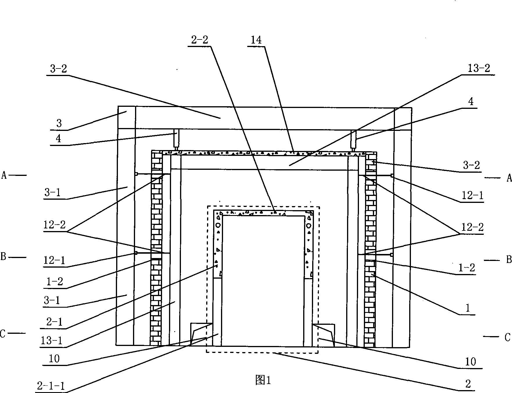
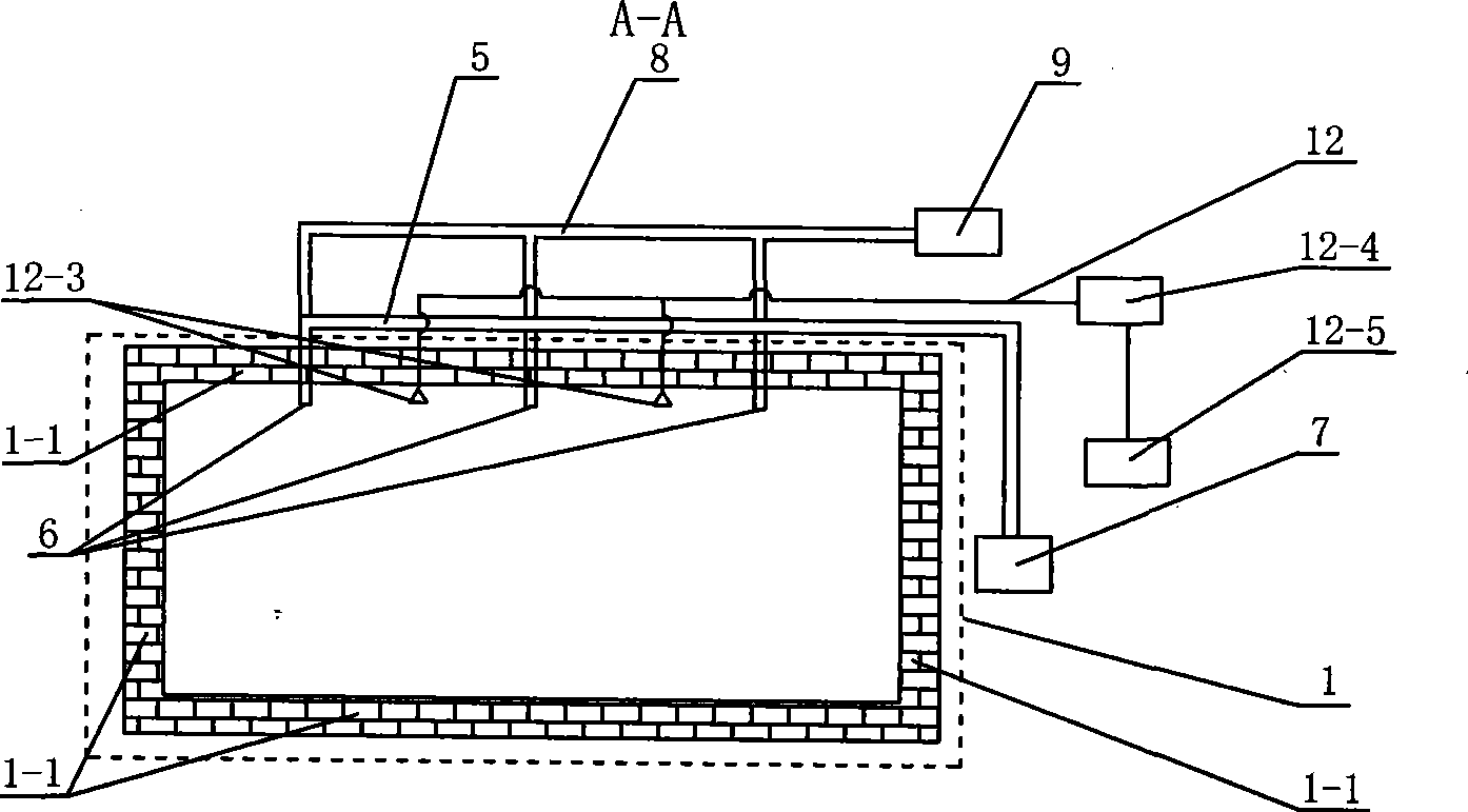
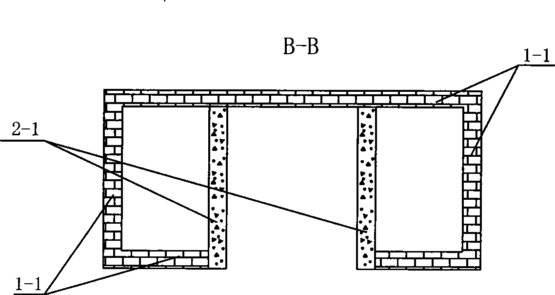
[0009] Embodiment 1: As shown in Figures 1 to 4, the fire resistance test device for measuring single-layer frames described in this embodiment includes an outer furnace body 1, an inner furnace body 2, a fuel pipeline 5, and four to eight combustion chambers. Nozzle 6, oil supply device 7, weathering pipeline 8, blower fan 9, flue exhaust duct 10 and measuring device 12, described test device also comprises reaction force frame 3 and two jacks 4, and described outer furnace body 1 is made of four external walls 1-1 surrounds a quadrangular prism-shaped furnace body, the inner furnace body 2 is composed of two inner walls 2-1 and an inner furnace cover 2-2, the inner furnace body 2 is arranged inside the outer furnace body 1, and the four The ~eight burners 6 are arranged in the furnace body 1, the oil supply device 7 communicates with the four to eight burners 6 through the fuel pipeline 5 respectively, and the blower 9 communicates with the four to eight burners 6 through the...
specific Embodiment approach 2
[0010] Specific embodiment two: As shown in Figure 1, the fire resistance test device for measuring single-layer frames described in this embodiment, the reaction frame 3 is composed of two columns 3-1 and beams 3-2, the The upper ends of the two upright columns 3-1 are connected together by a beam 3-2, and the lower ends of the two upright columns 3-1 are fixedly connected to the ground respectively. With such an arrangement, the jack 4 can be installed under the crossbeam 3-2, thereby achieving the purpose of applying load to the test member. Other components and connections are the same as those in the first embodiment.
specific Embodiment approach 3
[0011] Specific implementation mode three: as shown in Figure 1 and figure 2 As shown, the measuring device 12 described in this embodiment consists of a differential displacement meter 12-1, a high temperature resistant porcelain tube 12-2, four to eight thermocouples 12-3, a data acquisition instrument 12-4 and a computer 12 -5 components, one end of the four to eight high-temperature-resistant porcelain tubes 12-2 passes through the outer furnace body 1 and is arranged between the outer furnace body 1 and the inner furnace body 2, and the four to eight high-temperature-resistant porcelain tubes One end of 12-2 is respectively connected to the reaction frame 3 through a differential displacement gauge 12-1, and the four to eight thermocouples 12-1 are arranged between the outer furnace body 1 and the inner furnace body 2, and the thermocouples 12-1 is connected with computer 12-3 through data acquisition instrument 12-2. With this setting, it is possible to easily measure t...
PUM
 Abstract
Description
Claims
Application Information
 - R&D
- Intellectual Property
- Life Sciences
- Materials
- Tech Scout
- Unparalleled Data Quality
- Higher Quality Content
- 60% Fewer Hallucinations
Browse by: Latest US Patents, China's latest patents, Technical Efficacy Thesaurus, Application Domain, Technology Topic, Popular Technical Reports.
© 2025 PatSnap. All rights reserved.Legal|Privacy policy|Modern Slavery Act Transparency Statement|Sitemap|About US| Contact US: help@patsnap.com


