Circuit and method for data serial transmission
A serial transmission and circuit technology, applied in the field of data transmission method and its implementation circuit, can solve problems such as error accumulation, increased difficulty and cost, complex signal coding logic, etc.
- Summary
- Abstract
- Description
- Claims
- Application Information
AI Technical Summary
Problems solved by technology
Method used
Image


Examples
Embodiment 1
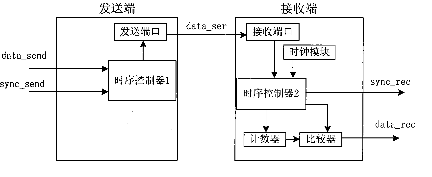
[0048] Such as figure 1 As shown, the present invention provides a serial transmission protocol circuit, the circuit includes sequentially connected timing controller 1, sending port, receiving port, timing controller 2, also includes clock module, counter and comparator, clock module, The counter and the comparator are connected to the timing controller 2 at the same time, and the counter is also connected to the comparator at the same time; in the application, the timing controller 1 and the sending port form the sending end, and the receiving port, the timing controller 2, the counter, the comparator and The local clock constitutes the receiving end. Of course, the composition of the above-mentioned sending end and receiving end is the minimum composition for realizing the purpose of the invention. In order to meet the needs of other application environments, other devices can be set in the circuit.
[0049]In the application, the timing controller 1 receives the first data...
Embodiment 2
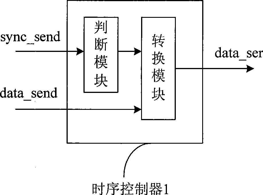
[0053] On the basis of Embodiment 1, for timing controller 1, it is preferably realized by the following structure, refer to figure 2 , the timing controller 1 includes a judging module, the judging module is used to judge whether the synchronous pulse sync_send is valid, and when the synchronous pulse sync_send is valid, pulses with different pulse widths are generated according to the detection result of the data signal data_send.
Embodiment 3
[0055] On the basis of Embodiment 1, for timing controller 2, it is preferably realized by the following structure, refer to image 3 , the timing controller 2 includes a counter enable module, which is used to send a counter enable signal within the effective pulse time when a valid pulse is detected, and enable the counter to count the pulse width of the signal data_ser.
[0056] Timing controller 2 can also include a comparator enable module, refer to image 3 , used to send a comparator enable signal after the effective pulse ends, enabling the comparator to compare the counting result with the natural number K preset by the system 0 Compare.
[0057] Timing controller 2 can also include an output module, refer to image 3 , after the comparator outputs the data signal, it outputs the pulse of the sync pulse sync_rec.
PUM
 Abstract
Description
Claims
Application Information