
Colineation structure of valve with electromagnetic drive

A technology of collinearity and structural size, applied in the direction of non-mechanically actuated valves, electromagnets with armatures, electromagnets, etc., can solve the problems of structural volume reduction, power reduction, etc., and achieve the effect of saving space

Active Publication Date: 2014-03-12
BURKERT WERKE
View PDF16 Cites 0 Cited by
  • Summary
  • Abstract
  • Description
  • Claims
  • Application Information

AI Technical Summary

Problems solved by technology

However, smaller dimensions lead to a reduction in the volume of the structure and, therefore, a reduction in the power that can be converted in the valve

Method used


Image

  • Colineation structure of valve with electromagnetic drive
  • Colineation structure of valve with electromagnetic drive
  • Colineation structure of valve with electromagnetic drive

Examples


Embodiment Construction

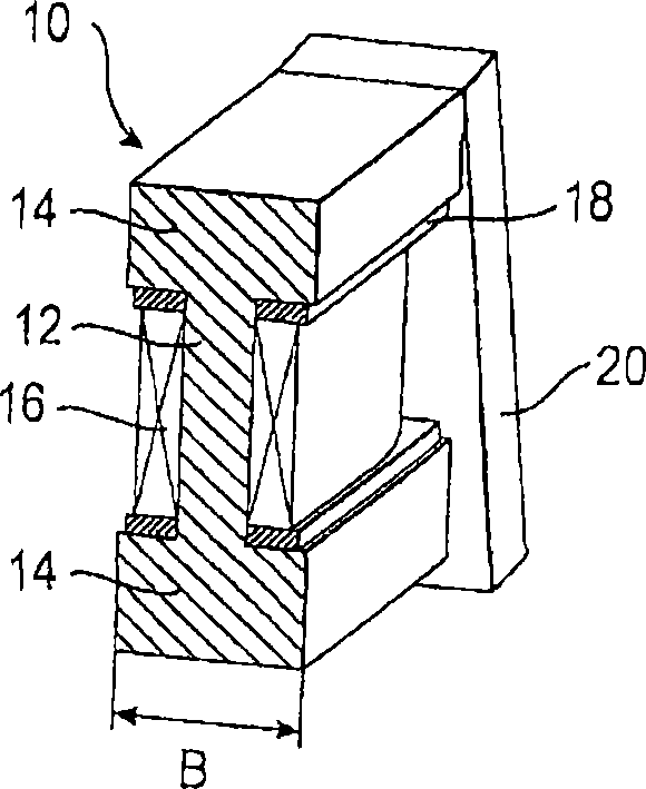
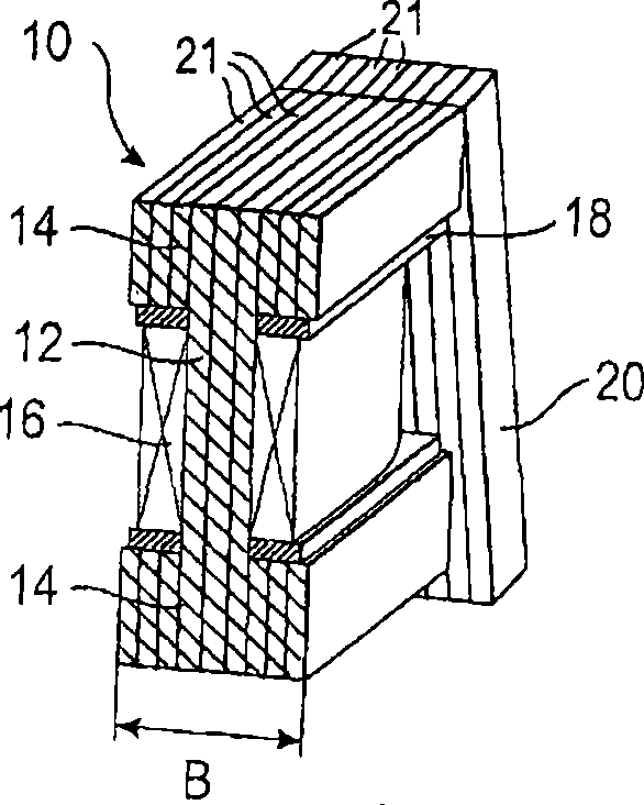
[0028] figure 2 A solenoid drive 10 is schematically shown for a valve according to the invention, more specifically a narrow valve with structural dimensions smaller than or equal to 5 mm, preferably approximately 4.5 mm. The driver 10 has a core 12 disposed between two poles 14 and formed in one piece therewith. The core 12 has disposed thereon a winding 16 formed of a plurality of copper turns (coils). There is also a coil former 18 arranged between the winding 16 and the pole 14, but this coil former differs from that of the prior art, at least in the direction of the dimension B which determines the structural dimensions of the valve, between the core 12 and the winding 16. There are no walls. The pole 14 protrudes over the winding 16 and cooperates with an armature 20 which is arranged relative to the pole 14 in such a way that it does not increase the structural size of the valve along the dimension B. and figure 2 Unlike the example shown, the coil carrier 18 can...


PUM


Abstract

A valve having an electromagnetic drive including a core that is arranged between two pole pieces and has a winding applied thereon which, at least in the direction of a dimension determining the structural size of the valve, rests on the core without a bobbin wall interposed.

Description

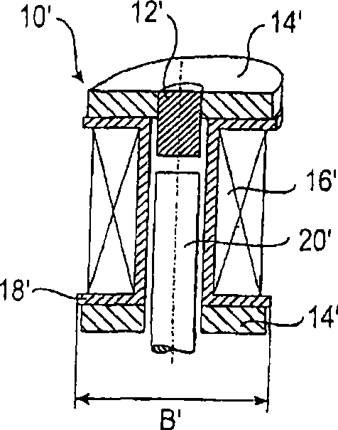
technical field [0001] The invention relates to valves with electromagnetic drives. Background technique [0002] There is always a growing demand for smaller valves in the market. However, smaller dimensions lead to a reduction in the structural volume and, therefore, a reduction in the power that can be converted in the valve. The maximum mechanical power output of an electromagnetic coil depends, for example, on many factors, but in particular on the structural volume and the ratio of the copper winding to the core cross-section accommodated in the coil. figure 1 An electromagnetic drive 10' for use in a valve according to the prior art is shown. The driver 10' comprises a core 12', two poles 14' and a winding 16' arranged on the wall of a former 18'. The partial core is formed as a movable lifting armature 20' and is arranged at a distance from the coil former 18' inside the coil former 18'. The dimensions determining the structural dimensions of the relevant valves ...

Claims


Application Information

Patent Timeline
Patent Type & Authority Patents(China)
IPC IPC(8): F01L9/04H01F7/14H01F7/08F16K31/06
CPCH01F7/081H01F7/1638F16K11/052F16K31/0675F16K31/0658H01F7/14F16K31/0682H01F2007/086F16K11/044
Inventor R·沙伊贝
Owner BURKERT WERKE
Learn More