Differential calibration

A technology of calibrator and difference value, applied in the direction of measuring devices, instruments, etc., can solve problems such as speed limit

Active Publication Date: 2009-05-13
RENISHAW PLC
View PDF3 Cites 26 Cited by
  • Summary
  • Abstract
  • Description
  • Claims
  • Application Information

AI Technical Summary

Problems solved by technology

However, when the contour of the workpiece or the small features to be scanned chang...

Method used


Image

  • Differential calibration
  • Differential calibration
  • Differential calibration

Examples


Embodiment Construction

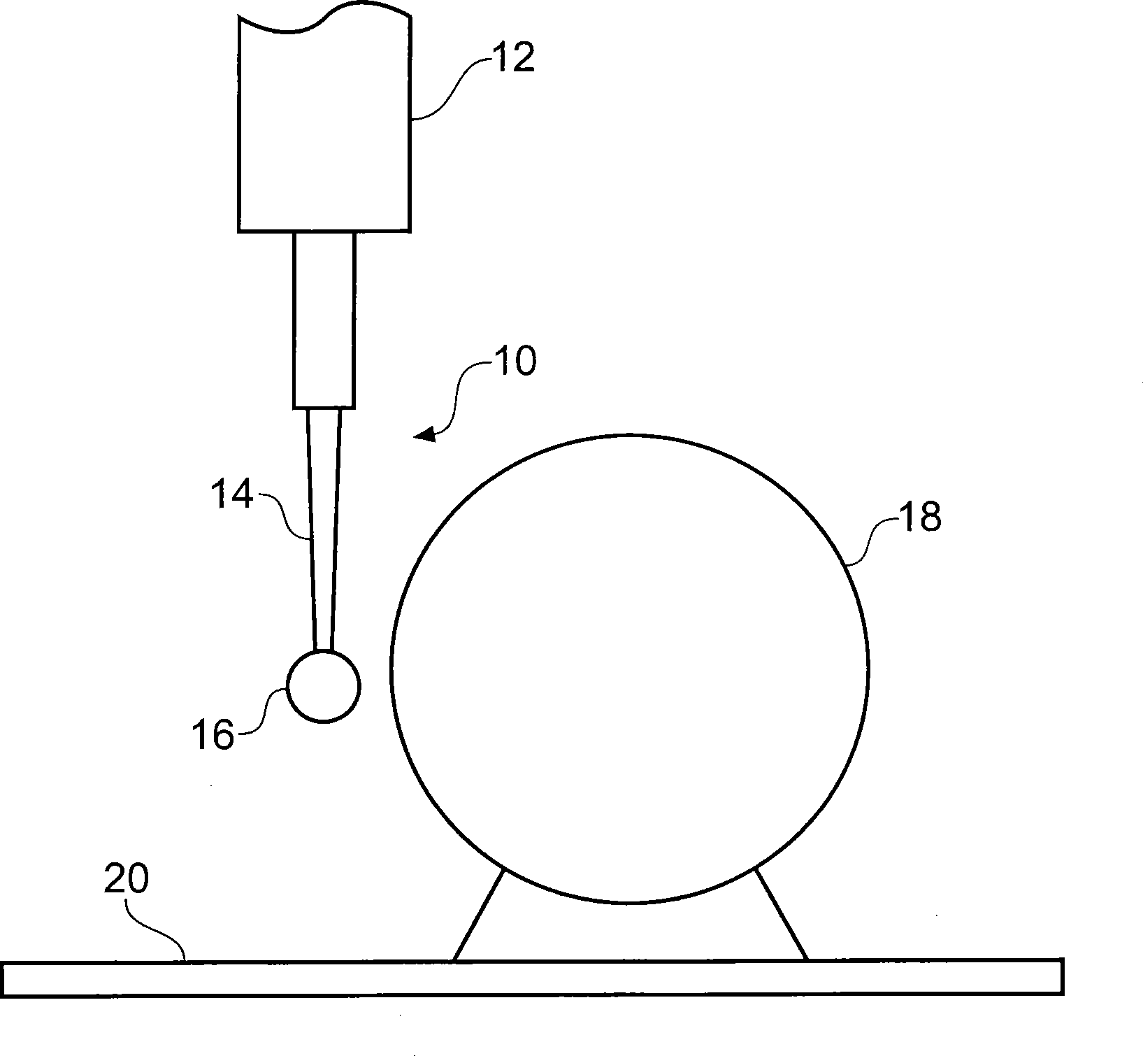
[0037] figure 1 A probe 10 is shown, linked at one end to the machine tool by a hollow shaft 12 , with a stylus 14 having a workpiece contact tip 16 located at the distal end of the probe 10 . The machine tool comprises a bed 20 on which a workpiece or in this case a calibration sphere 18 is located.

[0038] Probe 10 is an analog or scanning probe that produces probe deflection data related to any deflection of the stylus in its three orthogonal (Cartesian) scan axes. Here the raw probe deflection output is referred to as a, b, c coordinate values. The machine tool also includes a position encoder or similar for measuring the position of the hollow shaft in machine coordinate (X, Y, Z) geometry, ie providing so-called machine data.

[0039] In order to provide a measurement of the position of the stylus tip, measurements made in the probe (a, b, c) coordinate system must be converted to the machine (X, Y, Z) coordinate system. To provide this transformation, it is known t...


PUM


Abstract

A method of calibrating a measurement probe (10) mounted on a machine is described. The measurement probe (10) has a stylus (14) with a workpiece contacting tip (16). The method comprises determining a probe calibration matrix that relates the probe outputs (a,b,c) to the machine coordinate system (x,y,z.). The method comprising the steps of scanning a calibration artefact (18) using a first probe deflection (d1) to obtain first machine data and using a second probe deflection (d2) to obtain second machine data. The first and second machine data are used to obtain a pure probe calibration matrix in which any machine errors are substantially omitted. Advantageously, the method determines the pure probe matrix numerically based on the assumption that the difference between the first and second machine position data is known.

Description

technical field [0001] The invention relates to a method for calibrating a measuring probe mounted on a machine, in particular to a method for determining a probe calibration matrix. Background technique [0002] In measurement systems such as machine tools and measurement probes, there are various factors that affect the reading accuracy. These factors include errors, such as machine errors, which include: flatness and squareness errors; dynamic errors; and errors resulting from converting probe readings to machine axis readings. To moderate these effects, the machine and measurement probes need to be calibrated before any measurements are taken. [0003] Various techniques have been developed to calibrate such measuring equipment. These techniques involve scanning at different locations within the machine's operating envelope to form an error map of the machine. It is also known to scan a standard workpiece with different probe deflections in order to generate an error ...

Claims


Application Information

Patent Timeline
IPC IPC(8): G01B21/04
CPCG01B21/042
Inventor 亚历山大·坦南特·萨瑟兰
Owner RENISHAW PLC
Why Eureka
Try Eureka