Correction method of inner arc probe or outer arc probe in ultrasonic flaw detector

A calibration method, ultrasonic technology, which is applied in the direction of material analysis, instruments, and scientific instruments using sound waves/ultrasonic waves/infrasonic waves, which can solve problems such as the inability of users to judge and calibrate, increase the cost of users, and positioning deviations, so as to improve the use of Rate and use cycle, improve accuracy, shorten the effect of the cycle

Inactive Publication Date: 2010-09-15
符丰
View PDF5 Cites 9 Cited by
  • Summary
  • Abstract
  • Description
  • Claims
  • Application Information

AI Technical Summary

Problems solved by technology

[0002] At present, when the ultrasonic flaw detector uses inner and outer arc probes to detect, there is only one kind of "lip-shaped test block" used to measure the front edge b of the probe, but there is no way to measure the K value of the probe and the distance a traveled by the ultrasonic wave inside the probe. To make an accurate judgment, you can only make a rough calculation based on the K value provided by the probe manufacturer and the distance a that the ultrasonic wave travels inside the probe. However, the actual K value and a of the probe often have a little deviation from the manufactured value. In addition to the loss of the probe during use, the K value and a will change accordingly, but the user cannot judge and calibrate. When the probe is worn to a certain extent, the location of the defect will deviate, and the user can only replace the probe. will increase the cost of the user

Method used


Image

  • Correction method of inner arc probe or outer arc probe in ultrasonic flaw detector
  • Correction method of inner arc probe or outer arc probe in ultrasonic flaw detector
  • Correction method of inner arc probe or outer arc probe in ultrasonic flaw detector

Examples


Embodiment approach

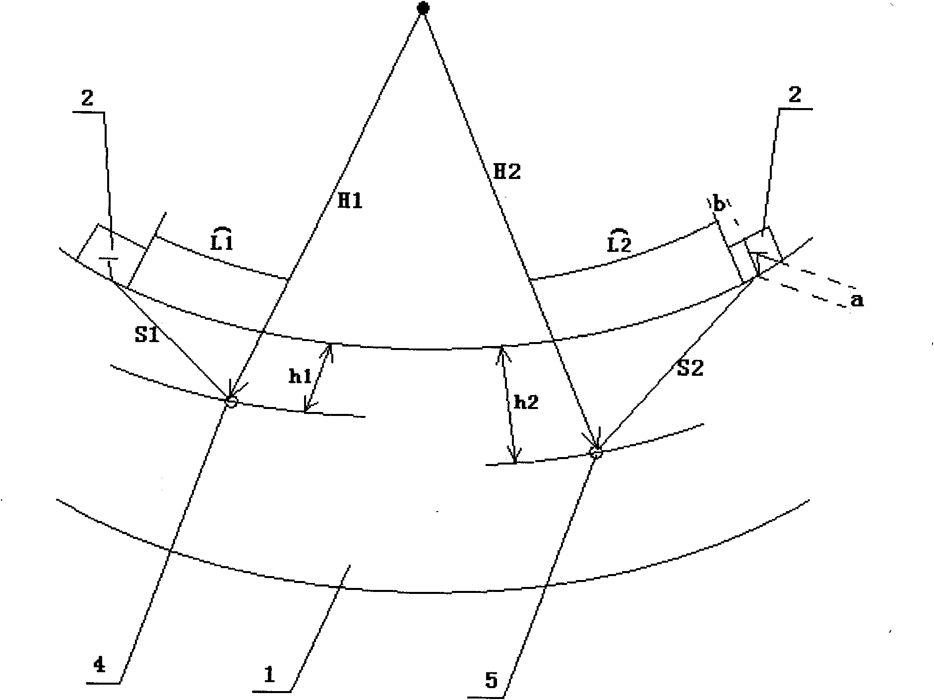
[0029] As an embodiment of the present invention, a method for calibrating the inner and outer circular arc probes of an ultrasonic flaw detector includes an ultrasonic flaw detector that transmits ultrasonic waves through the probe to detect flaws in workpieces. It is characterized in that the method includes the following steps in sequence:

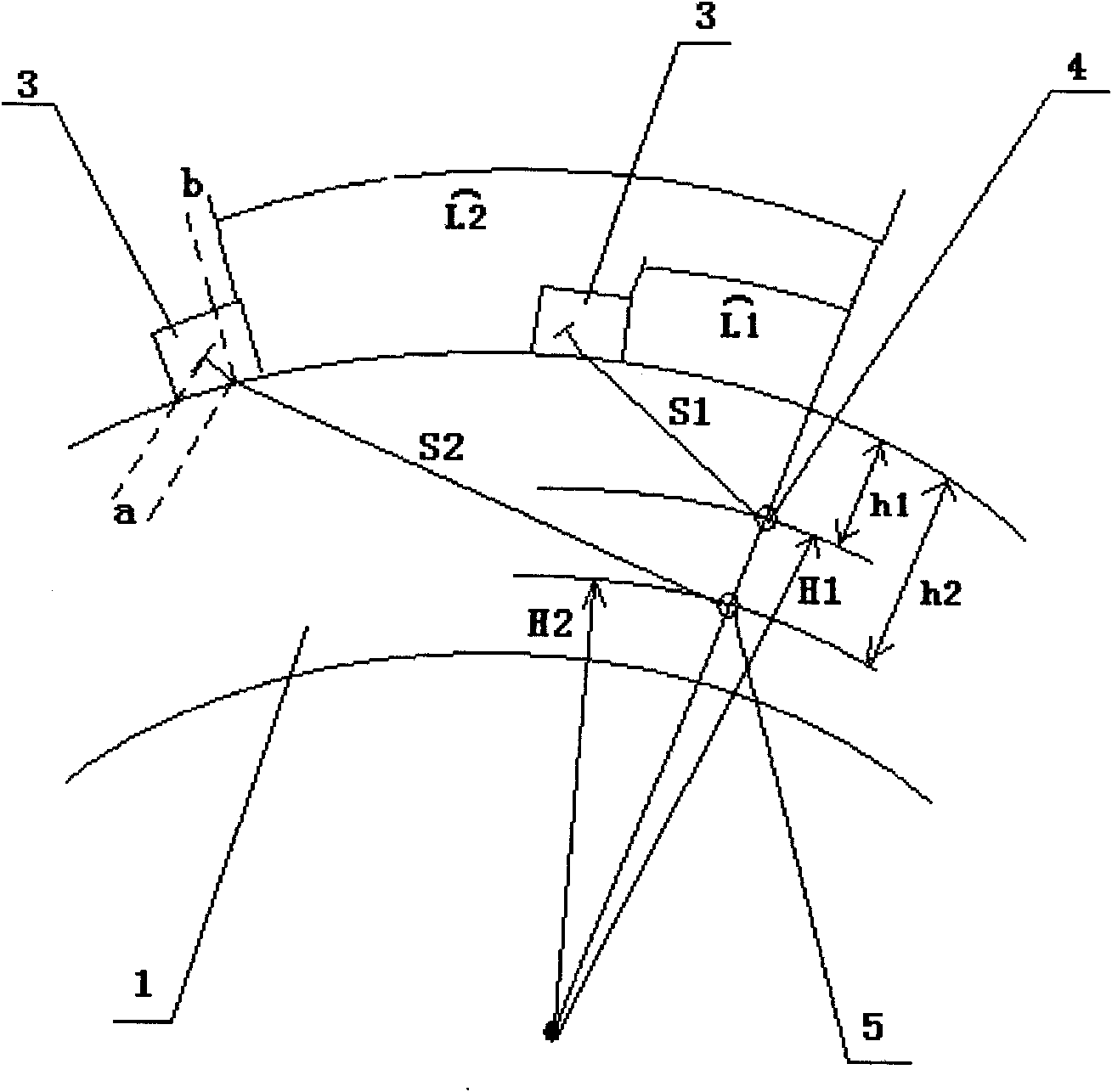
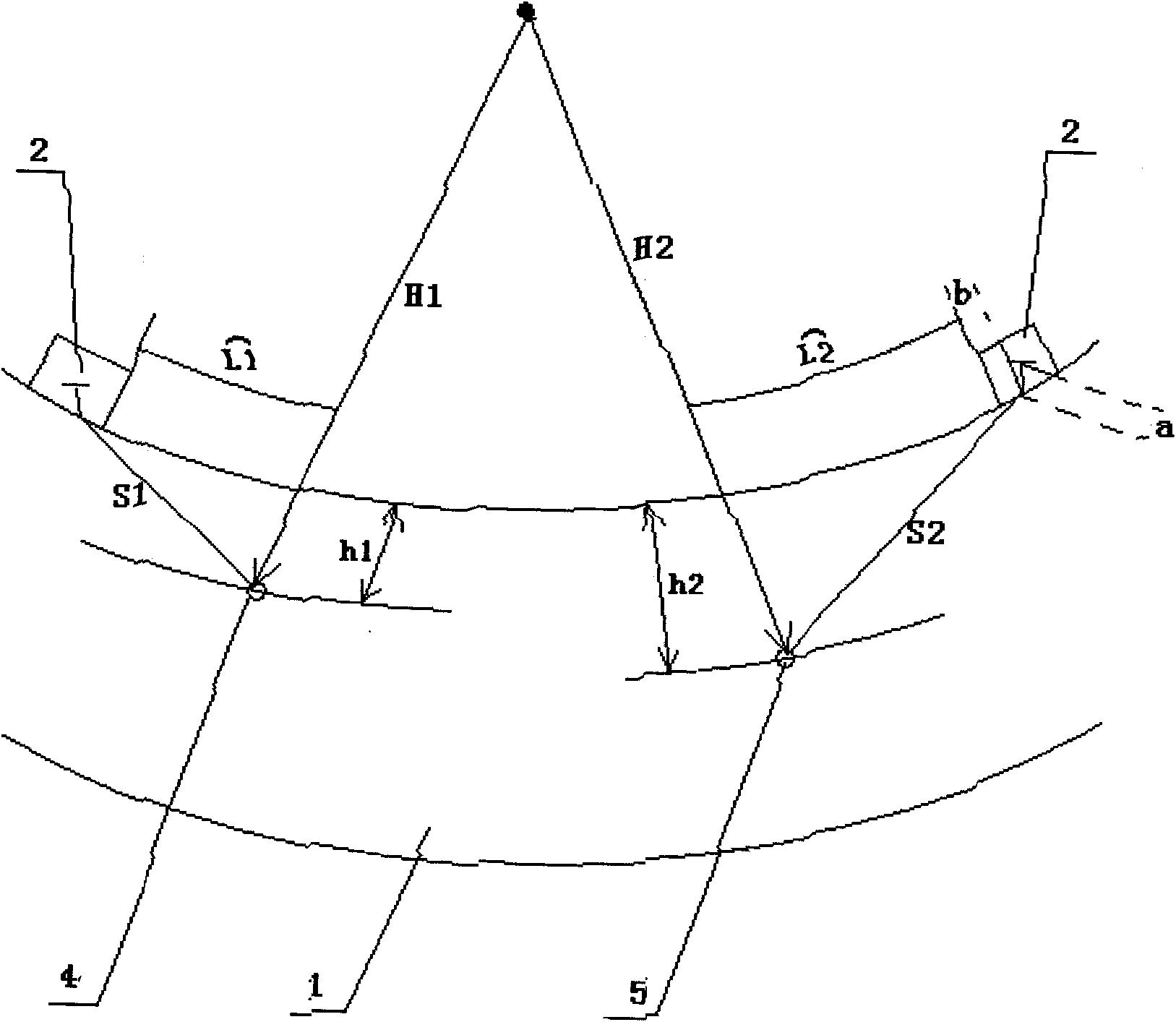
[0030] 1) Take a piece of test block 1 for probe calibration on the workpiece to be detected. The outer diameter of the test block 1 is R, the inner diameter is r, and an inner arc or outer arc probe 2, 3 for the ultrasonic flaw detector, and Drill two holes h at the distances H1 and H2 from the axis of the test block 1 along its axis 1 4 and hole h 2 5. The diameter of the two holes 4 and 5 is φ, and H1≠H2;

[0031] 2) if figure 1 , 2 As shown, use the inner arc or outer arc probes 2 and 3 to search back and forth for the hole h on the inner or outer wall of the test block 1 1 4. Until the hole h is displayed on the ultrasonic flaw...


PUM


Abstract

The invention discloses a correction method of an inner arc probe or an outer arc probe in an ultrasonic flaw detector, in particular to an instrument correction method by using an ultrasonic flaw detector, an inner arc probe or an outer arc probe which is used in the ultrasonic flaw detector. The correction method comprises the following steps of: cutting a block on a workpiece to be detected asa probe-connecting test block; respectively drilling two holes in different distances on the test block; searching the two holes back and forth by using the inner arc probe until the highest reflection echoes of the two holes are displaced on the ultrasonic flaw detector; respectively acquiring the distances from an ultrasonic wave emitting end in the probe to the two holes; measuring an arc length from the foremost border of the probe to the normal line of the two holes; and respectively acquiring a sound path a, a probe front border b and a probe K value in the inner arc probe or the outer arc probe according to a mathematical model. The invention fills in gaps of the test block and the correction method for acquiring a connection K value, a valve a and a valve b of the inner arc probe or the outer arc probe in the ultrasonic flaw detector, shortens the manufacture period, reduces the manufacture cost of the test block, improves the service rates of the probes and prolongs the life cycles of the probes.

Description

technical field [0001] The invention relates to an instrument calibration method, in particular to a method for calibrating inner and outer arc probes of an ultrasonic flaw detector. Background technique [0002] At present, when the ultrasonic flaw detector uses inner and outer arc probes to detect, there is only one kind of "lip-shaped test block" used to measure the front edge b of the probe, but there is no way to measure the K value of the probe and the distance a traveled by the ultrasonic wave inside the probe. To make an accurate judgment, you can only make a rough calculation based on the K value provided by the probe manufacturer and the distance a that the ultrasonic wave travels inside the probe. However, the actual K value and a of the probe often have a little deviation from the manufactured value. In addition to the loss of the probe during use, the K value and a will change accordingly, but the user cannot judge and calibrate. When the probe is worn to a cert...

Claims


Application Information

Patent Timeline
Patent Type & Authority Applications(China)
IPC IPC(8): G01N29/30
Inventor 符丰
Owner 符丰
Why Eureka
Try Eureka