Three-dimensional ultrasonic probe calibration device and method for calibrating three-dimensional ultrasonic probe

A technology of three-dimensional ultrasound and calibration devices, which is applied to measuring devices, material analysis using sound waves/ultrasonic waves/infrasonic waves, instruments, etc., can solve problems such as monotonous time-consuming, error, and high operator requirements, so as to improve efficiency and accuracy, and ensure Imaging clarity, avoiding the effect of additional calibration

Active Publication Date: 2019-12-10
SHANGHAI UNIV OF ENG SCI
View PDF5 Cites 10 Cited by
  • Summary
  • Abstract
  • Description
  • Claims
  • Application Information

AI Technical Summary

Problems solved by technology

[0003] The template based on the point model is one of the widely used models due to its simplicity, easy construction, and accurate imaging, but its disadvantage is that the ultrasonic plane and the target point need to be coplanar, so the existing probe calibration process based on the point model Usually it is tedious and time-consuming, and has high requirements for the operator
The traditional point model generally uses balls or cross lines to form single-point or multi-point targets, so the position of the point target cannot be directly known, and the point target needs to be scanned at multiple angles, requiring a large number of imaging images, so the ope

Method used


Image

  • Three-dimensional ultrasonic probe calibration device and method for calibrating three-dimensional ultrasonic probe
  • Three-dimensional ultrasonic probe calibration device and method for calibrating three-dimensional ultrasonic probe
  • Three-dimensional ultrasonic probe calibration device and method for calibrating three-dimensional ultrasonic probe

Examples


Embodiment Construction

[0033] The present invention will be described in detail below in conjunction with the accompanying drawings and specific embodiments.

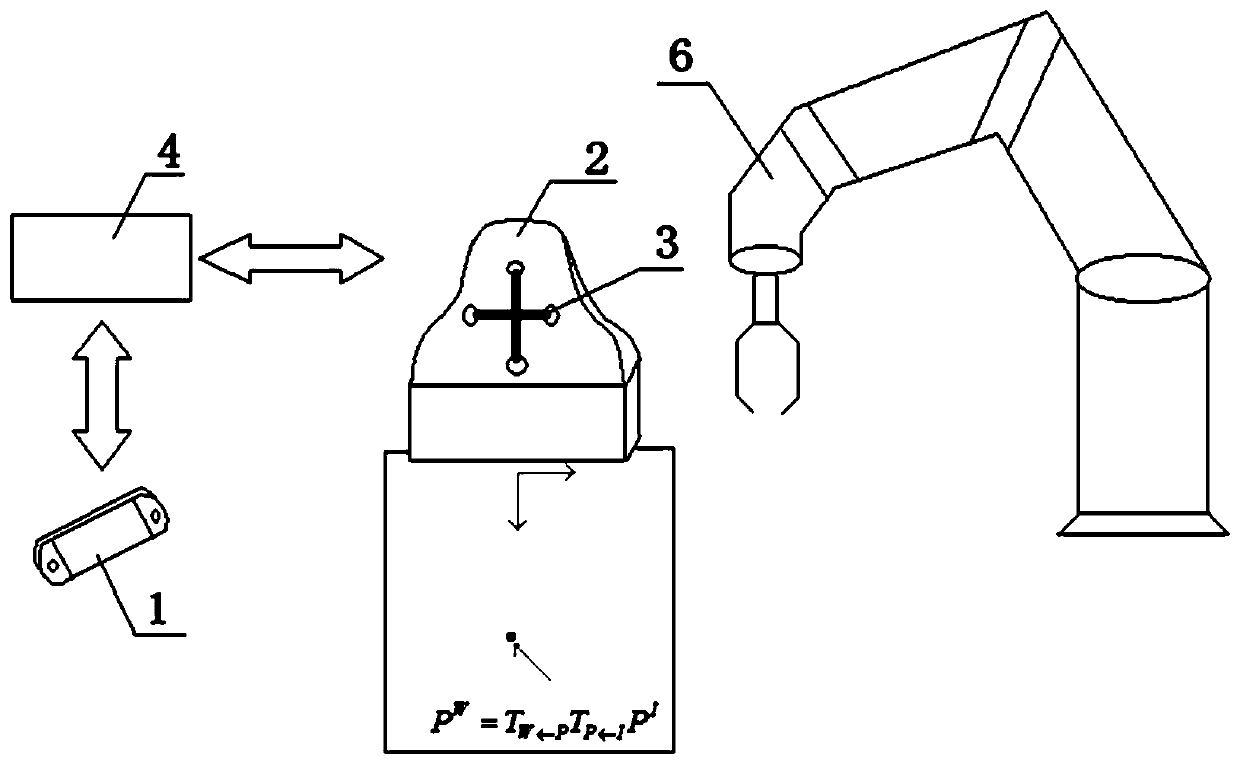
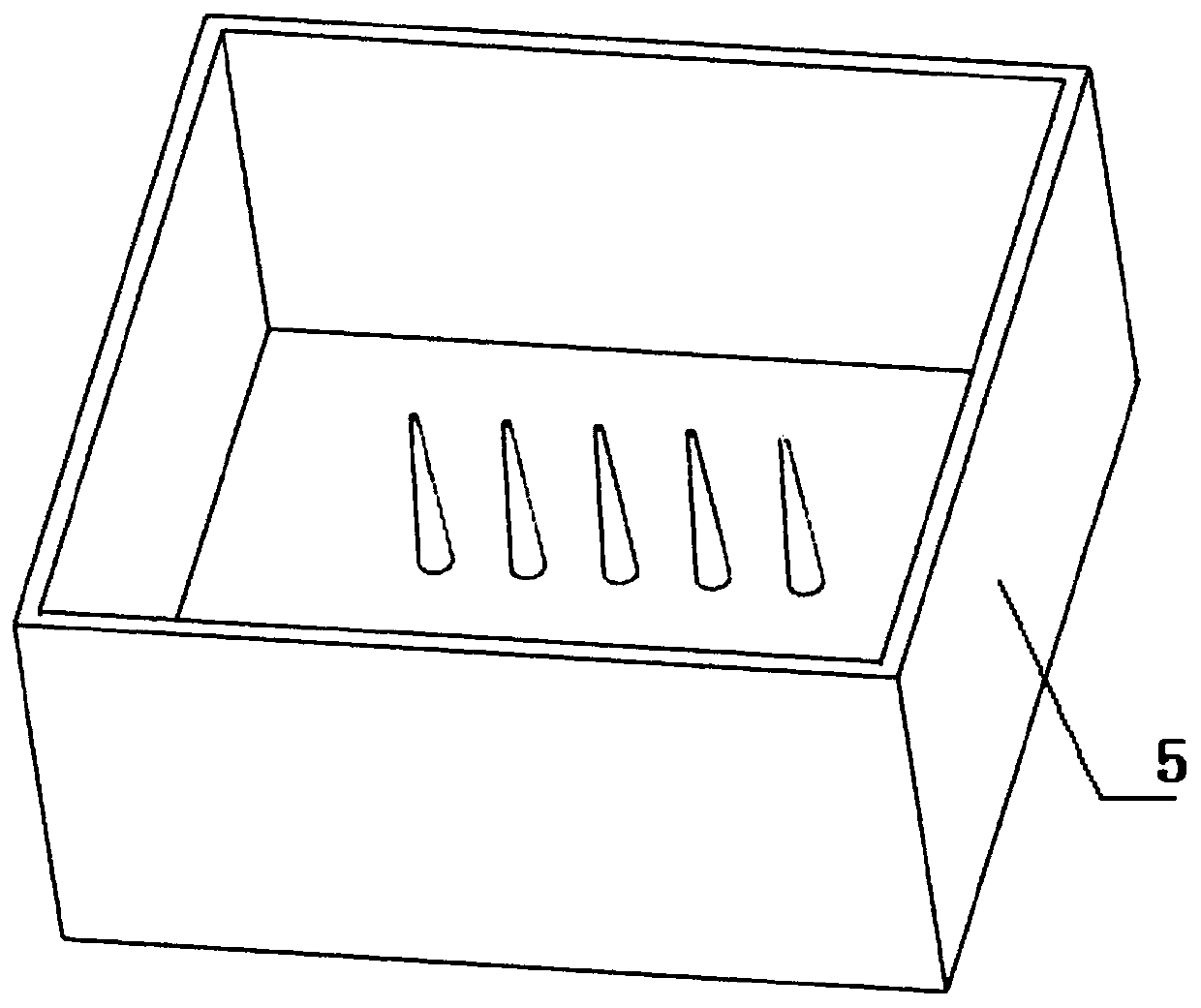
[0034] Such as figure 1 with figure 2 As shown, a three-dimensional ultrasonic probe calibration device includes an optical locator 1, an optical locating probe 3, an ultrasonic nondestructive flaw detector 2, a calibration template 5, a computer 4 and a mechanical arm 6, an optical locator 1 and an ultrasonic nondestructive flaw detector 2 They are respectively connected to the computer 4, the optical positioning probe 3 is fixed on the ultrasonic non-destructive flaw detector 2, the calibration template 5 is a water tank with multiple round tables at the inner bottom, and the optical positioning instrument 1 is used to track and obtain the position of the optical positioning probe 3 and attitude information;

[0035] The ultrasonic nondestructive flaw detector 2 is used to scan the calibration template 5 to obtain ultrasonic images;

[...


PUM


Abstract

The invention relates to a three-dimensional ultrasonic probe calibration device and a method for calibrating a three-dimensional ultrasonic probe. The three-dimensional probe calibration device comprises an optical positioning instrument, an optical positioning probe, an ultrasonic nondestructive flaw detector, a calibration template, a computer and a mechanical arm, wherein the optical positioning instrument and the ultrasonic nondestructive flaw detector are respectively connected with the computer, the optical positioning probe is fixed on the ultrasonic nondestructive flaw detector, the calibration template is a water tank of which the inner bottom is provided with a plurality of circular truncated cones, and counter bores are formed in the centers of the top surfaces of the circulartruncated cones. Compared with the prior art, the invention is based on optical localization, the improved calibration template is provided. Posture and pose information of the optical positioning probe is obtained through tracking, and the mechanical arm is adopted to clamp the ultrasonic nondestructive flaw detector for ultrasonic image scanning. And the optical positioning probe is directly contacted with the point target to obtain the position information of a point target, so that the operation difficulty of the calibration process is reduced, the additional calibration of the position information of the template point target is avoided, and the calibration precision and efficiency are improved.

Description

technical field [0001] The invention relates to the technical field of ultrasonic probe positioning, in particular to a three-dimensional ultrasonic probe calibration device and a method for calibrating a three-dimensional ultrasonic probe. Background technique [0002] Three-dimensional ultrasonic imaging uses a three-dimensional ultrasonic probe to scan an object and record its image, and then reconstruct and visualize the 3D volume of the object. It is a safe, cheap and easy-to-operate non-destructive testing technology. Calibrating the 3D ultrasound probe is a key step in realizing 3D visualization of ultrasound images. The spatial accuracy of the ultrasound system mainly depends on the accuracy of the ultrasound scanning plane relative to the probe marker coordinate system. The 3D ultrasound imaging system usually needs to use the ultrasound probe to perform imaging on the template. , and identify its features from the ultrasound image to minimize the residual error bet...

Claims


Application Information

Patent Timeline
IPC IPC(8): G01N29/30
CPCG01N29/30
Inventor 杨敏么娆
Owner SHANGHAI UNIV OF ENG SCI
Why Eureka
Try Eureka