
Feed gear of medical needle stand blade distributor

A technology of feeding device and needle holder, applied in mechanical conveyors, conveyors, conveyor objects, etc., can solve problems such as affecting the assembly process, low work efficiency, unqualified product hygiene requirements, etc., to improve production efficiency and ensure Hygienic standard, smooth and fast conveying effect

Active Publication Date: 2009-05-20
MAIDER MEDICAL IND EQUIP
View PDF0 Cites 59 Cited by
  • Summary
  • Abstract
  • Description
  • Claims
  • Application Information

AI Technical Summary

Benefits of technology

This patented technology allows for efficient and accurate supply of medical needles without human intervention or other factors that could affect their quality. It achieves this by delivering each individual needle's tip directly onto its corresponding sheath during manufacture while keeping it clean before being used next time. Additionally, there is also an improved way of handling the needled syringe after use safely.

Problems solved by technology

This patents describes how current methods involve attaching or inserting cut-edge parts onto needled blood collection syringe needles during manufacturers' production processes due to their high risk of contamination from handling them safely. Current automated systems may result in lower working efficiencies and increased waste generation compared to traditional ways of producing disposable items.

Method used


Image

  • Feed gear of medical needle stand blade distributor
  • Feed gear of medical needle stand blade distributor
  • Feed gear of medical needle stand blade distributor

Examples


Embodiment Construction

[0028] The following are specific embodiments of the present invention and in conjunction with the accompanying drawings, the technical solutions of the present invention are further described, but the present invention is not limited to these embodiments.

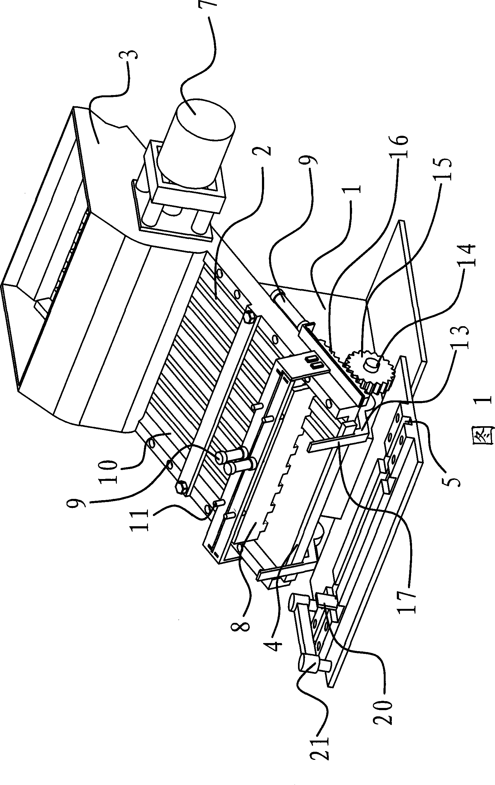
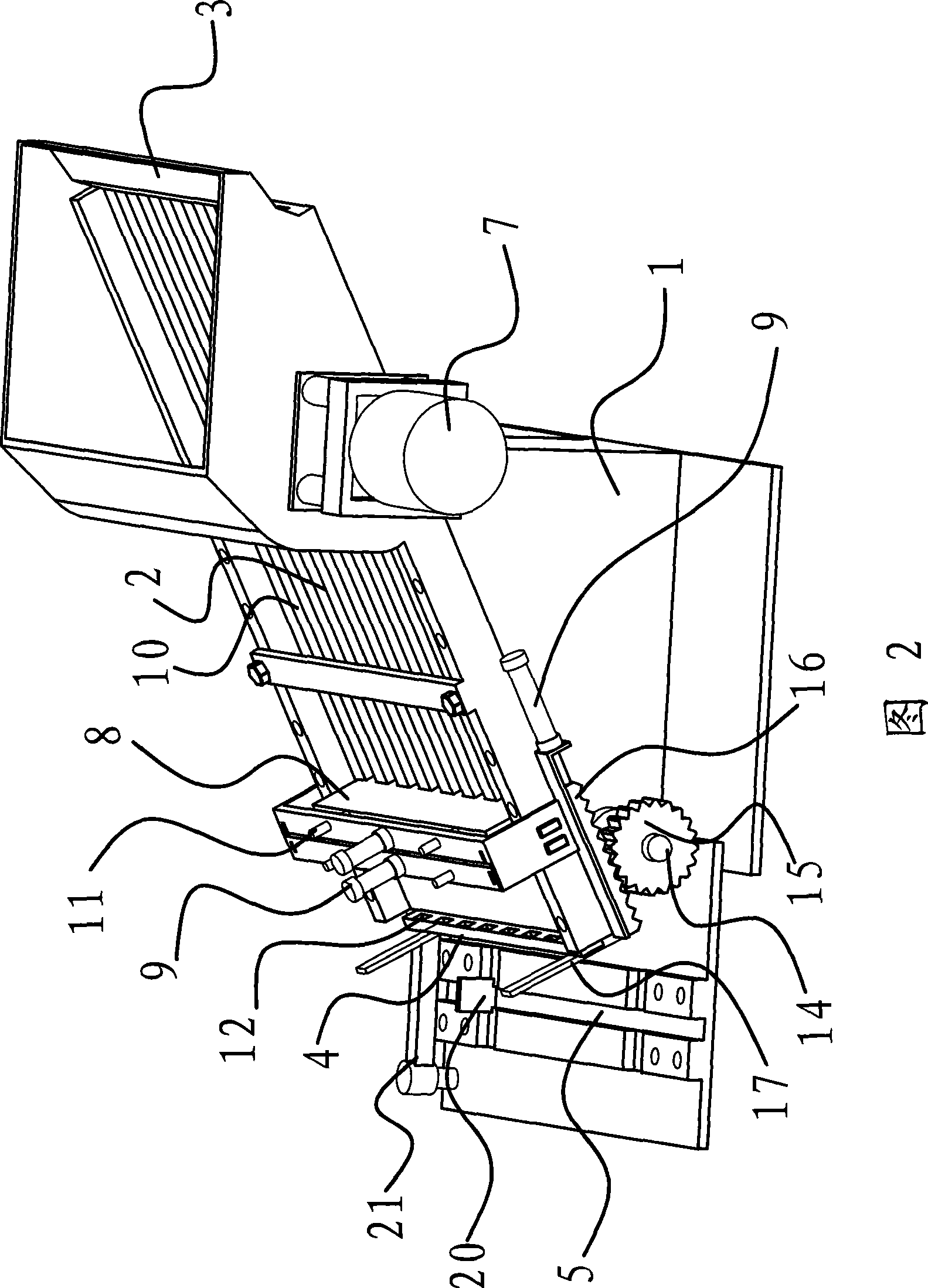
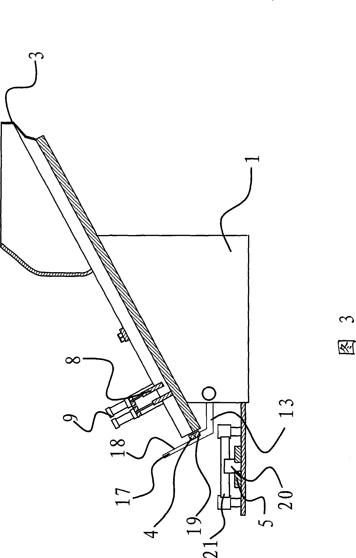
[0029] As shown in Fig. 1, Fig. 2, Fig. 3, Fig. 4 and Fig. 5, the feeding device of the medical needle seat blade distributor includes a vibration platform 1, a scraper plate 2, a hopper 3, a blade clamp 4, and a feeding guide rail 5. The material distribution mechanism and the transfer mechanism can automatically send the needle seat blades 6 to the blade holder 4 one by one, and send the blade holder 4 equipped with the needle holder blades 6 to the next station through the feeding guide rail 5 .

[0030] Specifically, the scraper 2 is arranged on the vibrating platform 1 , and the scraper 2 is placed obliquely, so that the needle holder blade 6 can slide down and move into the blade holder 4 by virtue of gravity. A hopp...


PUM


Abstract

The invention provides a feeding device of a medical needle stand vanes, belonging to the filed of mechanical technology and solving the technical problems of low work efficiency, pollution of the produced products and the like due to adoption of hand fitting of the existing feeding devices. The feeding device includes a vibration platform and a scratch board; a hopper is arranged at the upper end of the scratch board; a dividing mechanism which divides the needle stand vanes into a plurality of rows and delivers the needle stand vanes one by one is arranged at the lower end of the scratch board; a feeding lead rail is arranged at the position of a discharge hole of the dividing mechanism; a vane clamp which can slide on the feeding lead rail and can be separated from the feeding lead rail is arranged on the feeding lead rail; and a transferring mechanism which can transfer the vane clamp to the position of the discharge hole and to be connected therewith of the dividing mechanism and return to the feeding lead rail by the vane clamp is arranged on the vibration platform. The feeding device has the advantages of being available for automatically fitting the products, high in production efficiency, hygienic in products, etc.

Description


Claims


Application Information

Patent Timeline
Owner MAIDER MEDICAL IND EQUIP
Features
  • Generate Ideas
  • Intellectual Property
  • Life Sciences
  • Materials
  • Tech Scout
  • Unparalleled Data Quality
  • Higher Quality Content
  • 60% Fewer Hallucinations
Learn More