Support connection device for warp beam of warping machine
A technology for supporting connecting device and warping machine, applied in the direction of warping machine, other manufacturing equipment/tools, textiles and papermaking, etc., can solve the problems of uneven surface, yarn flushing, affecting the quality of yarn unwinding, etc. Achieve easy penetration, improve quality and save energy
- Summary
- Abstract
- Description
- Claims
- Application Information
AI Technical Summary
Problems solved by technology
Method used
Image
Examples
Embodiment 1
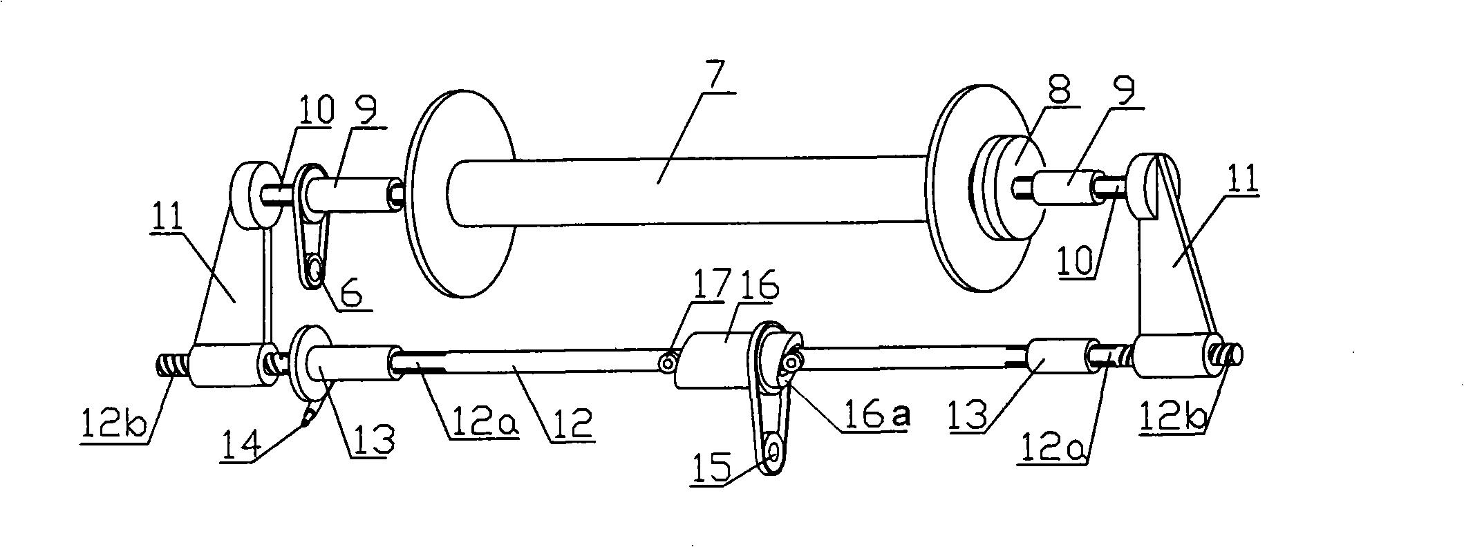
[0022] control figure 1 , the two spline shafts 10 are coaxially placed on the two ends of the warp shaft 7, the inner end of each spline shaft 10 is connected to the connecting disc 8, and the two connecting discs 8 are respectively pressed against the warp shaft 7. The corresponding end makes it connected with the warp beam 7 as a whole. The spline sleeve 9 is slipped on the spline shaft 10, and the winding transmission chain 6 made up of a belt and a pulley is connected to the outer peripheral side of the spline sleeve 9 on the right side. The warp shaft 7 and the spline shaft 10 rotate with the spline sleeve 9 .
[0023] The reciprocating shaft shift transmission mechanism 6 of this embodiment is mainly composed of a clapping arm 11, a clapping shaft 12, a spline sleeve 13, a cam 16, a roller 17, a clapping motor transmission chain 14 and an axial motor transmission chain 15. Clapping motor drive chain 14 is made up of worm gear reducer, belt and pulley, and axial motor ...
Embodiment 2
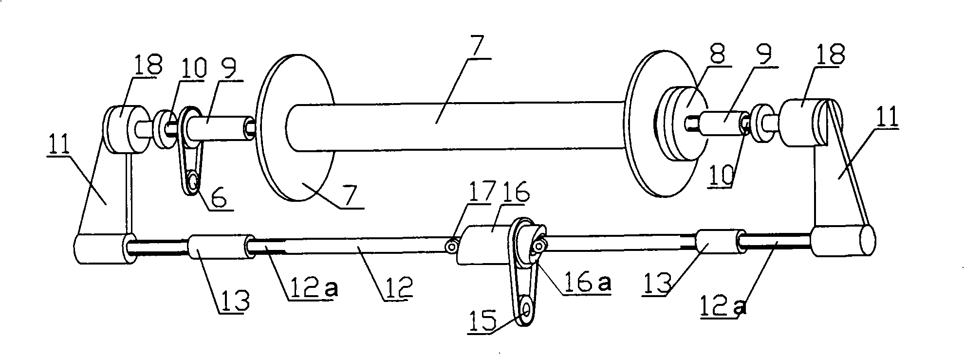
[0027] control figure 2 , the winding mechanism of this embodiment is the same as that of the above embodiment, and will not be repeated here. Its reciprocating shaft shift transmission mechanism is slightly different from the above-mentioned embodiment. It is mainly made up of clapping arm 11, clapping shaft 12, spline sleeve 13, cam 16, roller 17, cylinder 18 and axial motor drive chain 15. Axial motor transmission chain 15 is made up of belt and pulley. The two ends of clapping shaft 12 are provided with splines 12a, and two spline sleeves 13 are respectively slipped on the splines 12a. The linear and rotary motion of the snap-in shaft 12 is supported. The other ends of the two clapping arms are respectively connected to the rear seat of a cylinder, and the cylinder 18 is connected with the outer end of the corresponding spline shaft 10 by the thrust bearing installed at the top of the push rod thereon. When the cylinder works, the splined shaft 10 and the connecting d...
Embodiment 3
[0030] control image 3 , The winding mechanism part of the present embodiment is basically the same as that of Embodiment 1, except that the clapping or clapping of the two connecting discs 8 and the two ends of the warp beam 7 is done manually. When the two connecting discs 8 were connected or separated from the warp beam 7, the splined shaft 10 on the right side was fixed, and the splined shaft 10 on the left side could slide relative to the splined sleeve 9 on the left side, so that the connecting discs 8 and For the operation of clapping or clapping at the two ends of the warp beam 7, the connecting plate 8 and the warp beam 7 adopt bolts and nuts to clap and connect.
[0031] The corresponding reciprocating shaft shift transmission mechanism 6 is mainly composed of a cam 16 , a roller 17 and an axial motor transmission chain 15 . The cam 16 is sleeved on the spline shaft 10 in a cylindrical shape, and is coaxial with it. Equally, the two ends of cam 16 are provided wit...
PUM
 Abstract
Description
Claims
Application Information
 - R&D
- Intellectual Property
- Life Sciences
- Materials
- Tech Scout
- Unparalleled Data Quality
- Higher Quality Content
- 60% Fewer Hallucinations
Browse by: Latest US Patents, China's latest patents, Technical Efficacy Thesaurus, Application Domain, Technology Topic, Popular Technical Reports.
© 2025 PatSnap. All rights reserved.Legal|Privacy policy|Modern Slavery Act Transparency Statement|Sitemap|About US| Contact US: help@patsnap.com


