Folding frame - steel support - concrete combined shear wall and manufacturing method thereof
A combination of shear walls and concrete-filled steel tube technology, applied to walls, building components, and earthquake resistance, can solve problems affecting lateral force resistance and poor ductility, and achieve stable seismic performance, slow bearing capacity and stiffness decay, and increased use area effect
- Summary
- Abstract
- Description
- Claims
- Application Information
AI Technical Summary
Problems solved by technology
Method used
Image
Examples
Embodiment 1
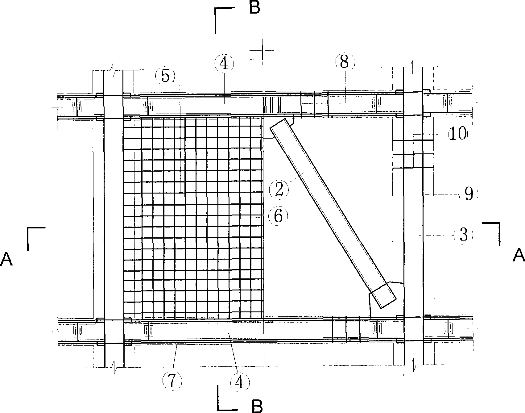
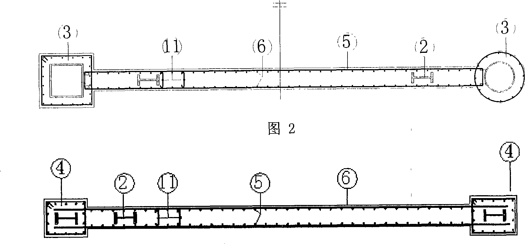
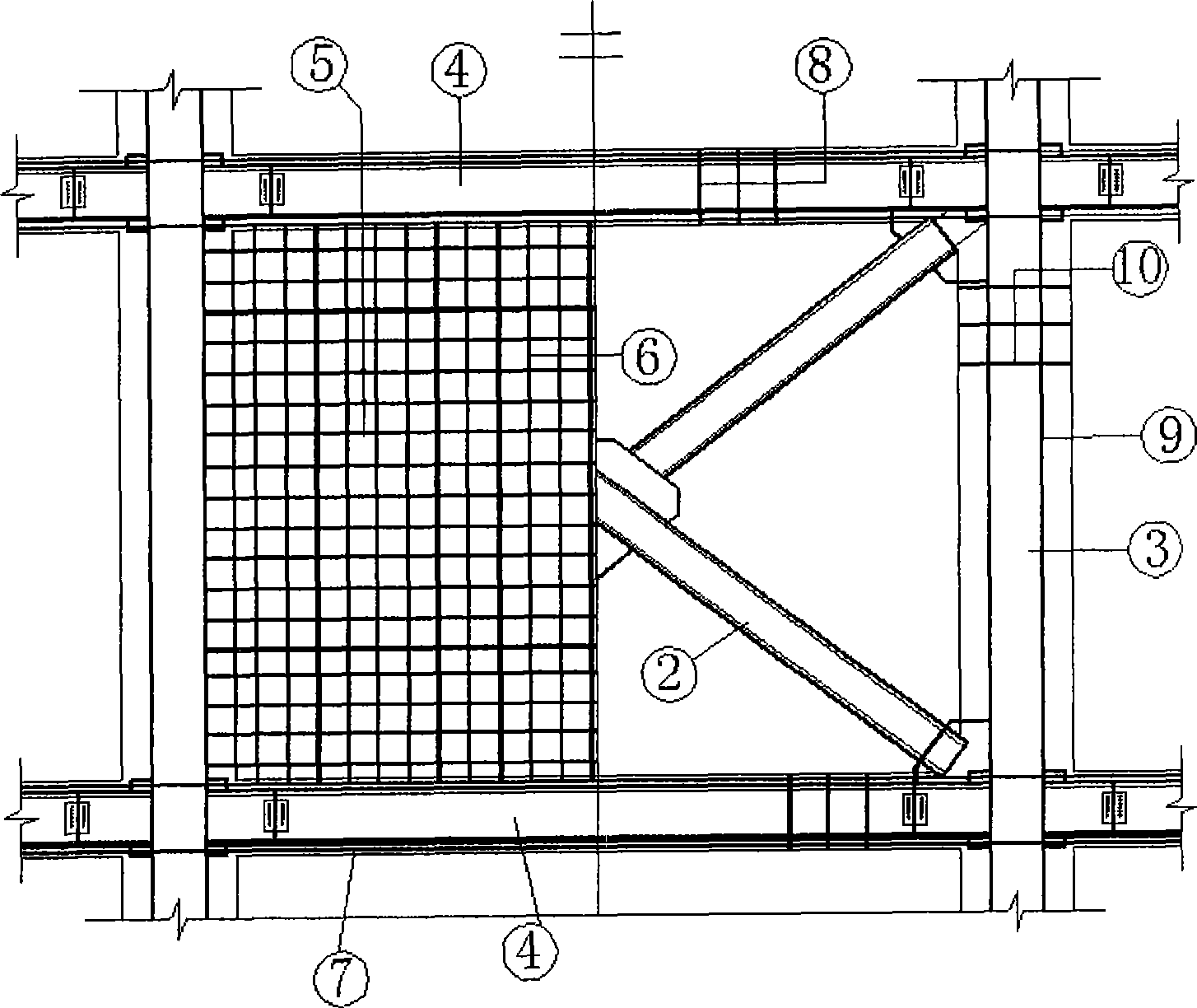
[0030] The schematic diagram of structural reinforcement of a structural unit of a composite frame-steel brace-concrete composite shear wall is shown in figure 1 , Figure 2 and image 3 shown. Concrete-filled steel tube core columns are arranged inside the concrete-filled steel tube composite columns 3; the frame beams of the shear wall are longitudinal bars 7 arranged around the steel beams 4, and rectangular stirrups 8 are evenly bound along the longitudinal bars 7 of the beams, and the rectangular stirrups 8 of the frame beams are Evenly distributed to the beam end; the reinforcement of the shear wall panel is: on both sides of the width direction of the wall panel, the transverse reinforcement 5 and the vertical reinforcement 6 of the shear wall panel are evenly arranged in the horizontal and vertical directions respectively, and are bound at the intersection fixed to form two pieces of steel mesh, the two ends of the horizontal steel bar 5 and the vertical steel bar 6 ar...
Embodiment 2
[0040] The second structural form of composite frame-steel brace-concrete composite shear wall is as follows: Figure 4 As shown, the X-shaped steel concealed support 2 is set inside the two steel meshes of the shear wall panel, and its upper end extends into the joint between the steel tube concrete composite column 3 and the upper frame beam, and connects with the steel tube concrete composite column 3 and the upper frame. The beams are medium-sized steel beams with 4 connections. The lower end extends into the joint between the concrete-filled steel tube composite column 3 and the lower frame beam, and is connected with the concrete-filled steel tube composite column 3 and the medium-sized steel beam 4 of the lower frame beam. Other aspects are the same as the first form.
Embodiment 3
[0042] The third structural form of composite frame-steel brace-concrete composite shear wall is as follows: Figure 5 As shown, the eight-shaped steel concealed support 2 is set inside the two steel meshes of the shear wall panel, and its upper end extends into the upper frame beam to connect with the beam medium-sized steel beam 4, and its lower end extends into the steel pipe concrete composite column 3 and the lower frame Among the nodes of the beam, it is connected with the concrete-filled steel tube composite column 3 and the medium-sized steel beam 4 of the lower frame beam. Other aspects are the same as the first form.
PUM
 Abstract
Description
Claims
Application Information
 - R&D
- Intellectual Property
- Life Sciences
- Materials
- Tech Scout
- Unparalleled Data Quality
- Higher Quality Content
- 60% Fewer Hallucinations
Browse by: Latest US Patents, China's latest patents, Technical Efficacy Thesaurus, Application Domain, Technology Topic, Popular Technical Reports.
© 2025 PatSnap. All rights reserved.Legal|Privacy policy|Modern Slavery Act Transparency Statement|Sitemap|About US| Contact US: help@patsnap.com


