LED road lamp
A technology for LED street lights and light poles, which is applied in circuit layout, use of semiconductor lights, outdoor lighting, etc.
- Summary
- Abstract
- Description
- Claims
- Application Information
AI Technical Summary
Problems solved by technology
Method used
Image
Examples
Embodiment 1
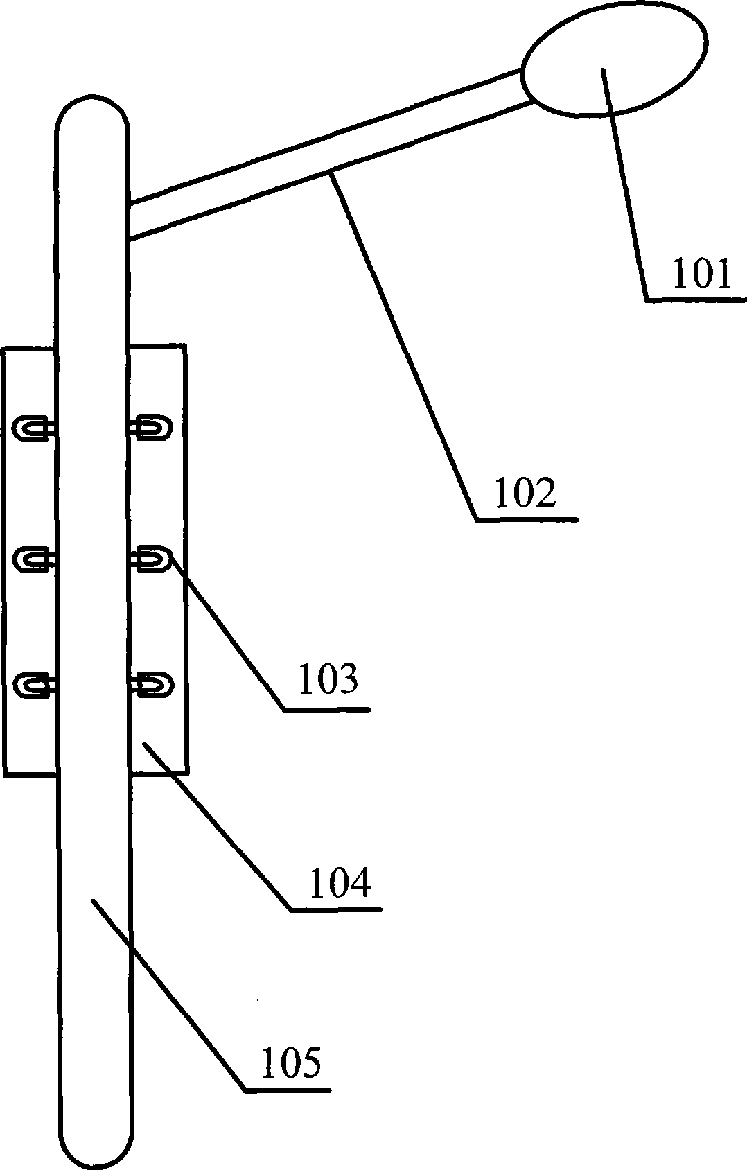
[0024] Such as figure 1 As shown, the LED street lamp of this embodiment includes a lamp post and a lamp body 101, wherein the lamp post is used to support the entire LED street lamp, so that the LED street lamp can be fixed on a specific place, and the lamp body 101 is fixed on the On the light pole, the pole 102 can enable the lamp body 101 to protrude above the road surface of the carriageway for road surface illumination of the carriageway.
[0025] The lamp body 101 is provided with a lamp holder and a PCB board; the lamp holder is used to fix the PCB board, and LED light-emitting diodes and other electronic components are installed on the PCB board, and the LED light-emitting diodes are mainly used for traffic lane Road lighting; other electronic components include resistors used to prevent excessive current of each LED light-emitting diode, control modules used to control LED light-emitting diodes, and so on.
[0026] The lamp holder can be set as a plane plate, or a c...
Embodiment 2
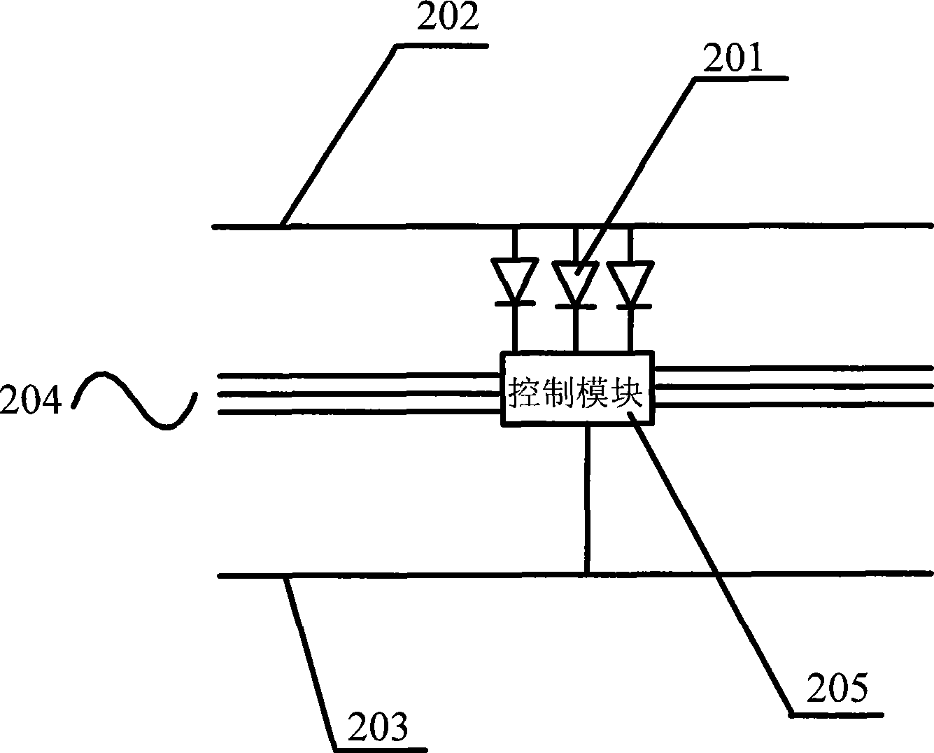
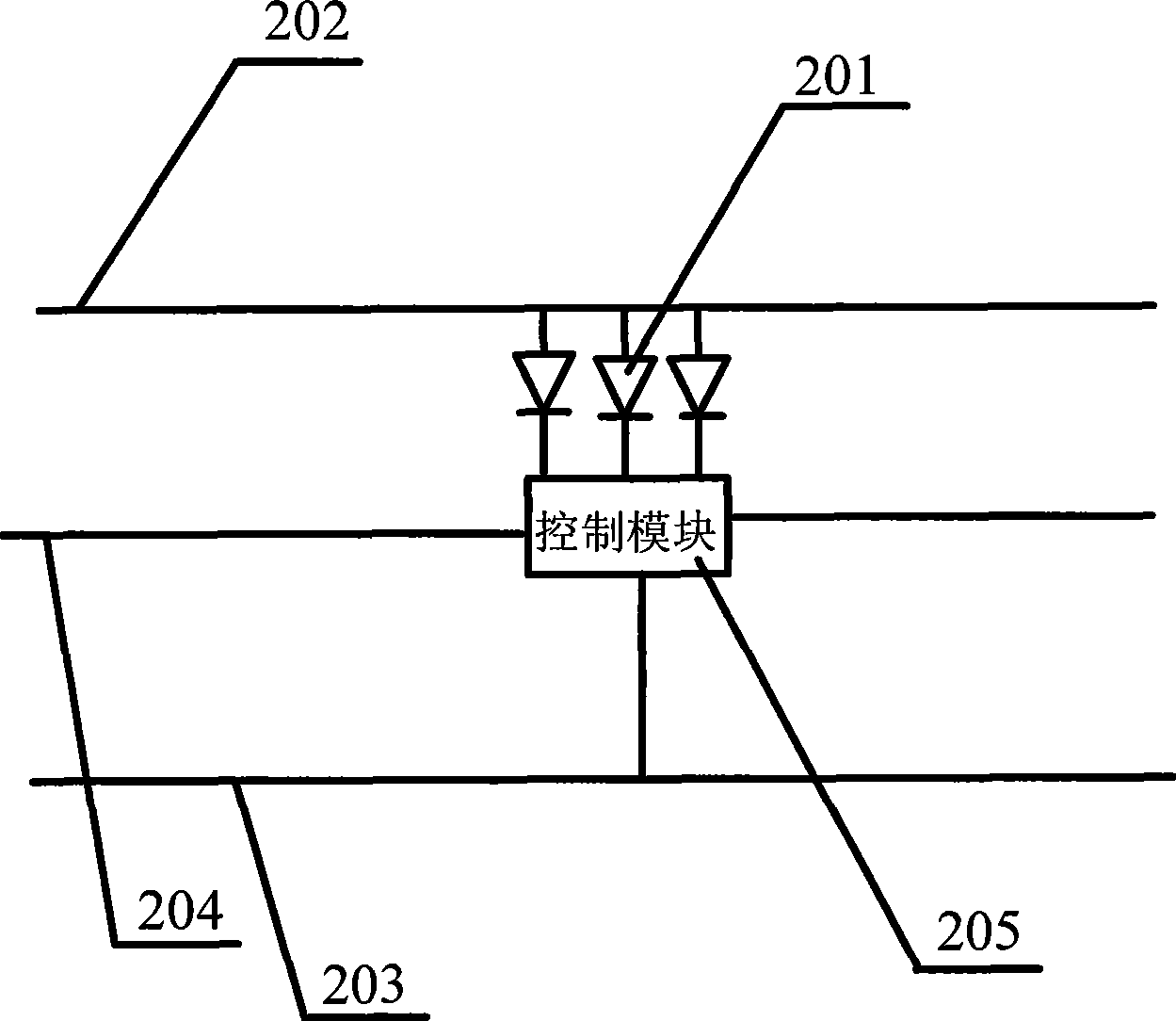
[0044]On the basis of each example in Embodiment 1, a plurality of positive power lines 202 and a plurality of negative power lines 203 may also be arranged on the PCB 201 .
[0045] Each power line can be set to include multiple positive power lines and multiple negative power lines. Each positive power line and each negative power line are respectively connected to an external power supply to provide voltage for each group of LED light-emitting diodes to ensure that the LED street light The normal operation of each group of LED light-emitting diodes and other electronic components; other electronic components can be control modules, or resistors installed to prevent excessive current.
[0046] Multiple pairs of positive and negative power lines can be connected to LED light-emitting diodes and other electronic components respectively. When a certain pair of positive and negative power lines is disconnected, it will not affect the normal operation of other positive and negativ...
Embodiment 3
[0051] In the above-mentioned embodiments, the rigid support body 105 can be set as a hollow tubular support body, and the end of the tubular support body can be provided with end caps to prevent water vapor, fallen leaves, dust, etc. from falling into it. Setting the support body in a tubular shape can reduce the material of the support body, reduce the weight, and facilitate transportation under the same function of support, and because there is a cavity in the tubular support body, each connecting line can be placed in the inner cavity, and the LED street light The overall beauty.
[0052] A plurality of small holes are provided on the tubular support body 105, each LED light emitting diode is arranged on the outer surface of the support body 105, each LED light emitting diode passes through each small hole, and is fixed on the inner surface of the tubular support body.
[0053] Generally, a small hole can be provided corresponding to each LED light-emitting diode, and a sm...
PUM
 Abstract
Description
Claims
Application Information
 - R&D Engineer
- R&D Manager
- IP Professional
- Industry Leading Data Capabilities
- Powerful AI technology
- Patent DNA Extraction
Browse by: Latest US Patents, China's latest patents, Technical Efficacy Thesaurus, Application Domain, Technology Topic, Popular Technical Reports.
© 2024 PatSnap. All rights reserved.Legal|Privacy policy|Modern Slavery Act Transparency Statement|Sitemap|About US| Contact US: help@patsnap.com


